
Introduction
We are going to break down the framing into 11 framing modules that will be assembled on the ground in parallel with other construction processes.
This is the how-to for the modules of the 1st floor. Starting from the south, they are labeled 1-3 with an "a" and "b" distinction referencing their location on either west or east respectively.
Tools
Parts
No parts specified.
-
-
Gather materials for Mod. 1a+b
-
4:2x4x6'
-
1/2 sheet of 3/4"x4'x8' OSB (other 1/2 will be used for Mod. 1b)
-
1/2 sheet of 1/2"x4'x8' plywood (other 1/2 will be used for Mod. 1b)
-
~16: 3-1/8" construction screw
-
~16: 1-5/8" coated deck screw
-
-
-
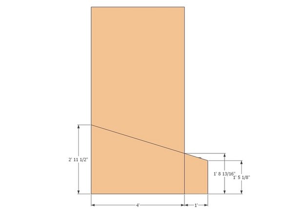
Use two people to make the proper cuts at the dimensions in the graphic at a 17 degree angle on the miter saw.
-
Simultaneously, use the other two people in your group to assemble the framing pieces using two 3-1/8" construction screws per connection, screwing perpendicular to the bottom plate and top diagonal pieces.
-
-
-
Exterior Sheathing for Module 1a
-
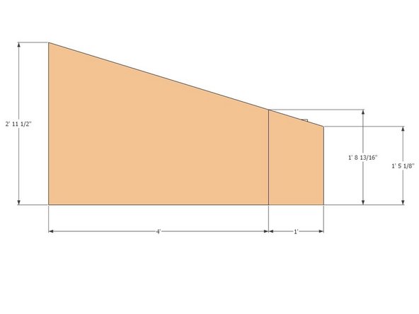
Cut the 17 degree angle on the piece by marking the two vertical distances and snapping a guide chalk line to connect the two. Use a 7-1/4"circular saw to make the cut.
-
Keep the rest for future use for Mod. 1b and the small 1" wide pieces in this module
-
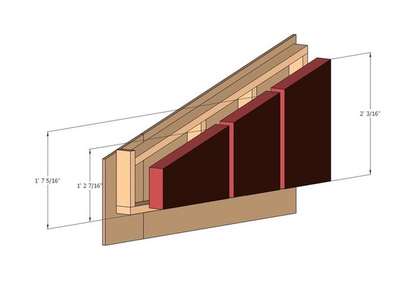
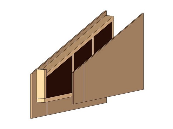
Align the sheathing with a 3/4" overhang on the left and a 6" overhang from the bottom plate. The offset will create 3/4" gap on the right side for the previous module to attach to. The top overhang should be 1.5" to cover the top plate that will unify the modules during installation. The bottom overhang will cover the width of the bond beam.
-
Fasten the 3/4" OSB to the framing using 1-5/8" coated deck screws around the perimeter and interior studs @ approximately 16" spacing.
-
repeat above procedure for the smaller piece of module
-
remember that the "scraps" from this 3/4"x4'x8' sheet will be used for the exterior sheathing for Mod. 1b
-
-
-
Interior sheathing for module 1a
-
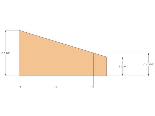
Cut the 17 degree angle on the piece by marking the two vertical distances and snapping a guide chalk line to connect the two. Use a 7-1/4"circular saw to make the cut.
-
Keep the rest for future use for Mod. 1b and the small 1" wide pieces in this module
-
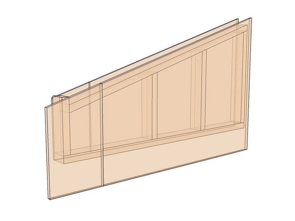
Align the sheathing with a 3/4" overhang on the left flush with the bottom plate. The offset will create 3/4" gap on the right side for the previous module to attach to. The top overhang should be 1.5" to cover the top plate that will unify the modules during installation. The bottom overhang will cover the width of the bond beam.
-
Fasten the 1/2" plywood to the framing using 1-5/8" coated deck screws around the perimeter and interior studs @ approximately 16" spacing.
-
repeat above procedure for the smaller piece of module
-
remember that the "scraps" from this 1/2"x4'x8' sheet will be used for the interior sheathing for Mod. 1b
-
-
-
Module 1b has the same assembly instructions as Module 1a except that the interior and exterior sheathing are inverted because they are mirror images of one another.
-
Follow module 1a steps 1-5 for module 1b, but reverse the sides of the sheathing so that module 1b has the exterior sheathing on the opposite side as module 1a.
-


Cancel: I did not complete this guide.
One other person completed this guide.