
-
-
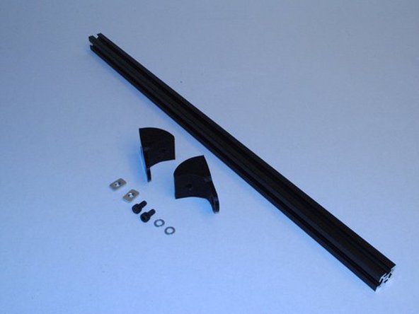
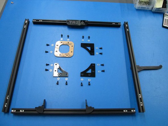
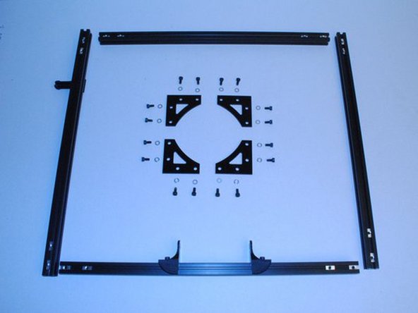
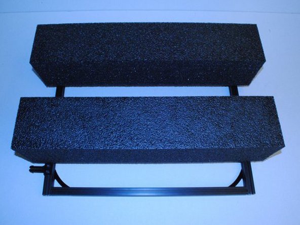
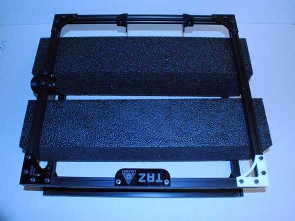
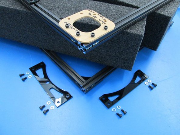
GATHER PARTS AND TOOLS FOR FRAME ASSEMBLY
-
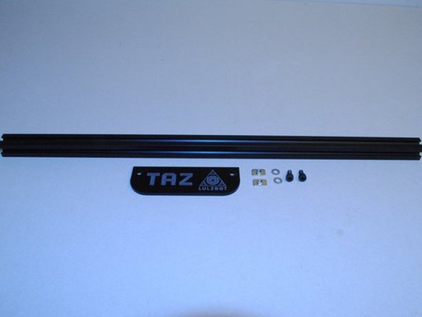
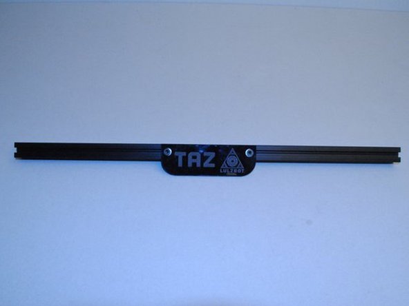
Components: Z top flat Z top flat side Frame connector Name Plate Y mount chassis Z motor mounts, Left and Right Spool Arm
-
Feed tube holder Extrusion, 500mm Black, not tapped Extrusion, 500mm Black, tapped on one end M5 x 10 SHCS M5 x 14 SHCS M5 Washer M5 T-nuts
-
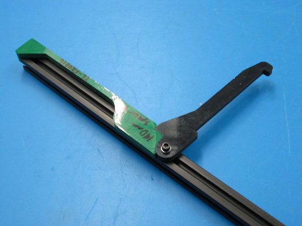
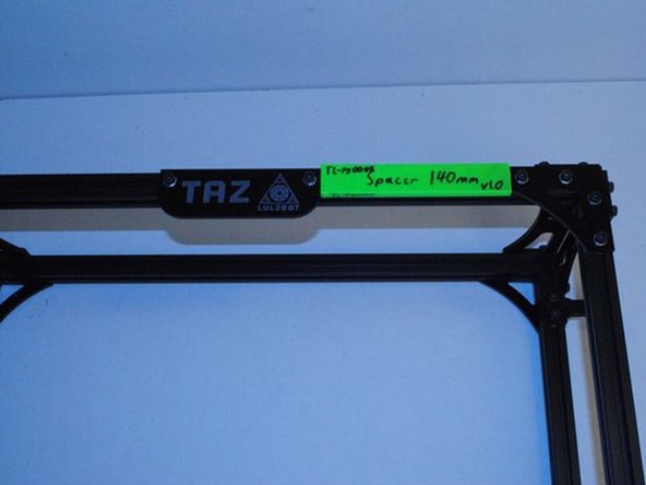
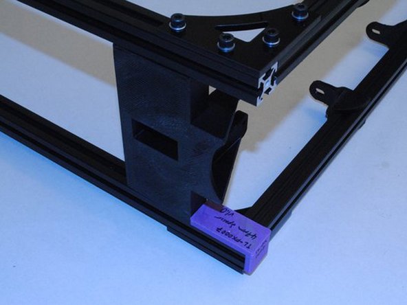
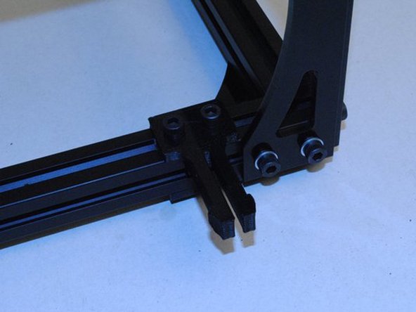
Tools:TL-FX0001, 140mm Spacer TL-FX0009, TL-FX0021, 48mm Spacer TL-FX0016 4mm Allen Driver
-
Photo 1: TL-FX0001, 140mm Spacer
-
Photo 2 - TL-FX0016
-
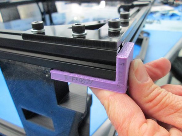
Photo 3 - TL-FX0021, 48mm Spacer
-
-
-
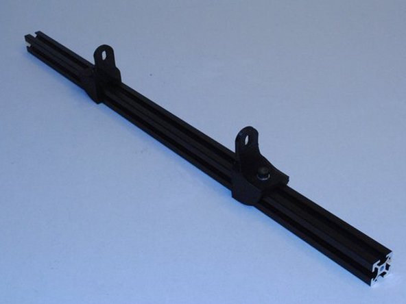
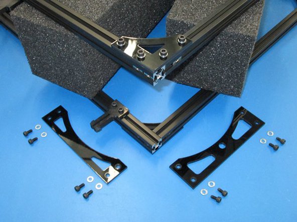
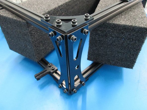
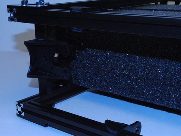
INSTALL Y MOUNT CHASSIS ONTO EXTRUSIONS - Build 2 of these assemblies.
-
Install two Y mount chassis onto Extrusion with no taps using M5 x 10 SHCS, M5 Washers and M5 T-nuts.
-
Take note of the direction of the Y mounts, the tall flat sides must face each other.
-
The location is not important at this point. Snug them down just enough to not slide around during the rest of the assembly.
-
Have you assembled 2 of these?
-
-
-
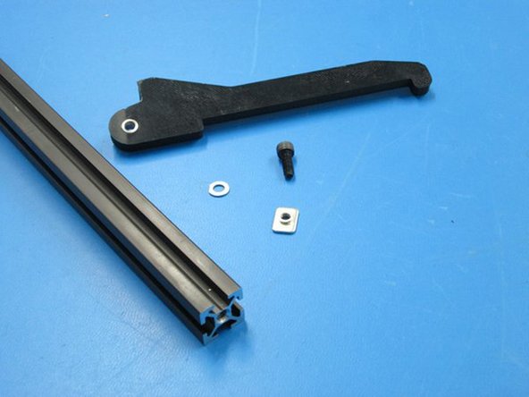
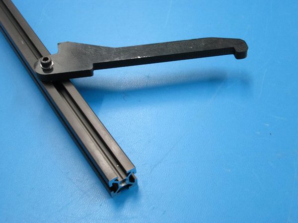
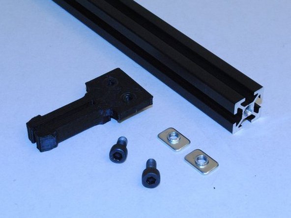
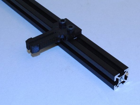
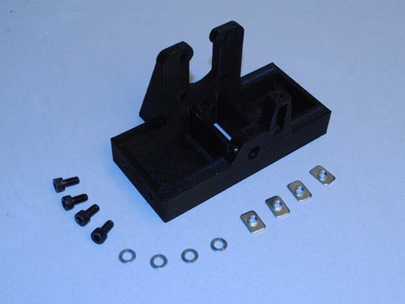
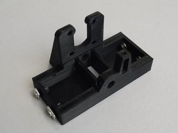
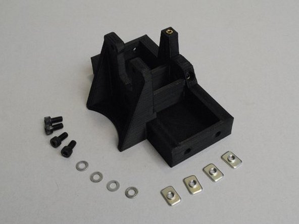
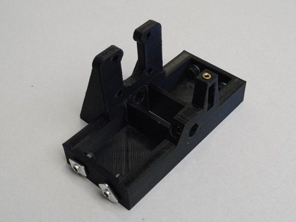
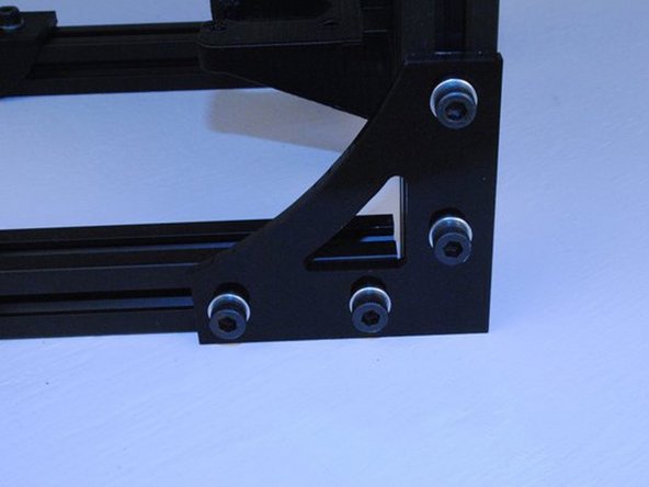
INSTALL Z MOTOR MOUNT RIGHT
-
Install 4x M5 x 10 SHCS, M5 Washers and M5 T-nuts into the Z motor mount right as shown.
-
Slide the motor mount into the bottom of the frame and set it's height with the 48mm fixture.
-
Photo 1 - Parts required to install the Z motor mount right
-
Photo 2 - Hardware installed for insertion
-
Photo 3 - Z motor mount right installed
-
-
-
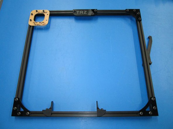
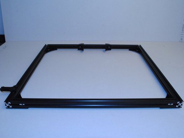
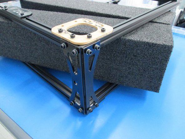
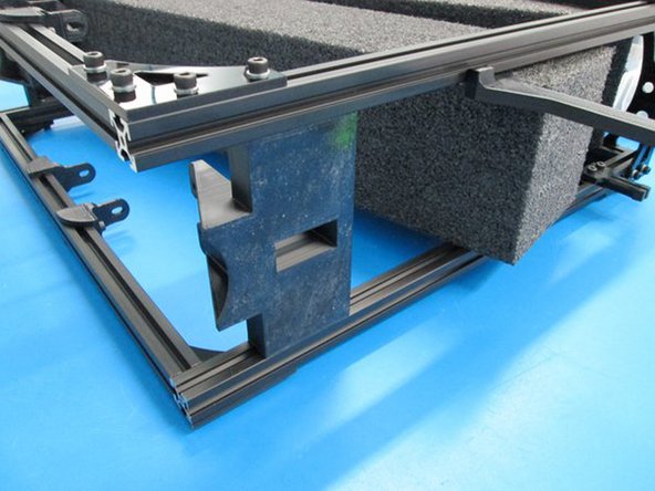
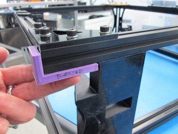
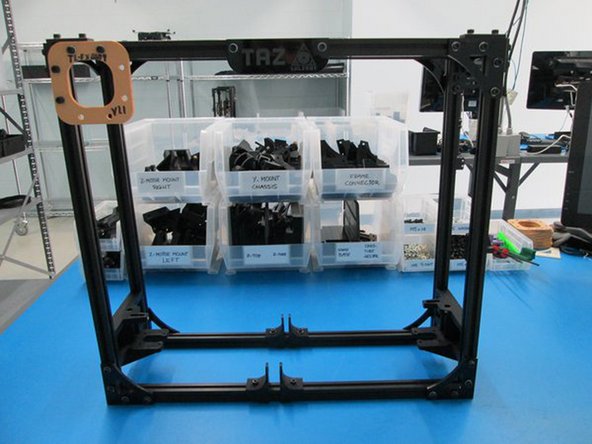
SQUARE FRAME, SET SPACING AND TORQUE BOLTS
-
Set the frame up on a flat surface.
-
Close any gaps there may be at the ends of the extrusions.
-
Make sure all parts are straight on the assemble with edges flush with the extrusion.
-
Photo 1 - Frame Assembly
-
Photo 2 - Example of Extrusion gaps
-
Photo 3 - Example of flush edges
-
-
-
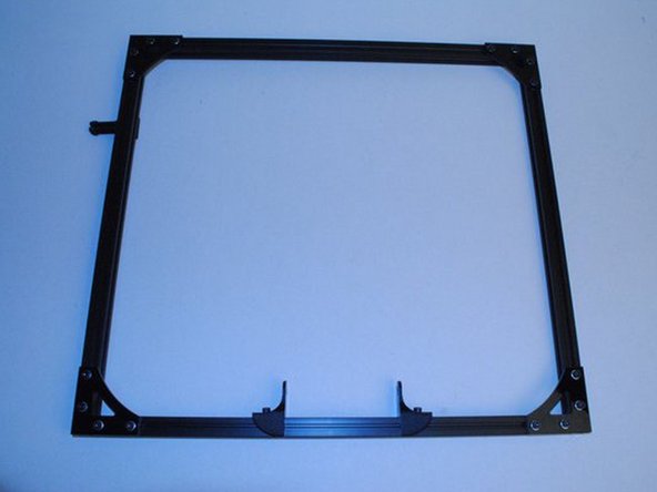
SQUARE FRAME, SET SPACING AND TORQUE BOLTS (continued)
-
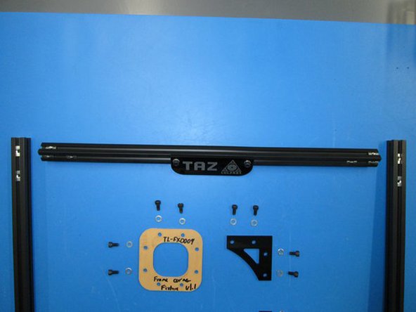
Using fixtures, set the location of the Name plate, Z motor mounts and Feed tube holder.
-
Tighten all the bolts at this point.
-
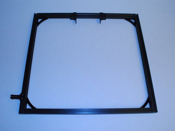
Is the frame square?
-
Are all the gaps at the ends of the extrusion closed?
-
Are the edges of the parts flush with the extrusion?
-
Are all the bolts tight? Are there 2x M5 T-nuts in the top front extrusion and 2x M5 T-nuts in the left front extrusion?
-
Photo 1 - Set Name plate spacing and tighten bolts -- Photo 2 - Z Motor Mount height -- Photo 3 Location of Feed tube holder
-


Cancel: I did not complete this guide.
One other person completed this guide.