Difficulty
Moderate
Steps
39
Time Required
12:00:00

In Progress
This guide is currently being written. Reload periodically to see the latest changes.
Quiz
0
Introduction
-
-
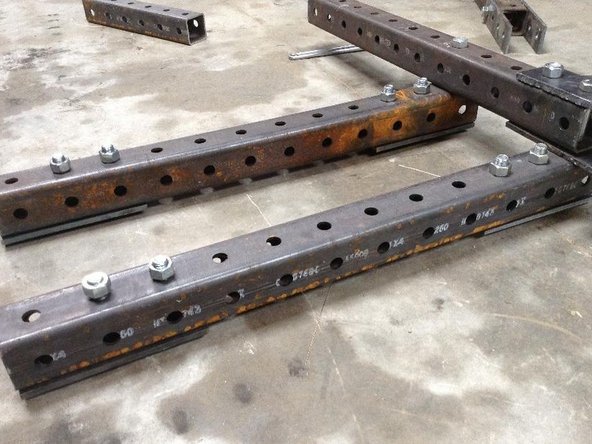
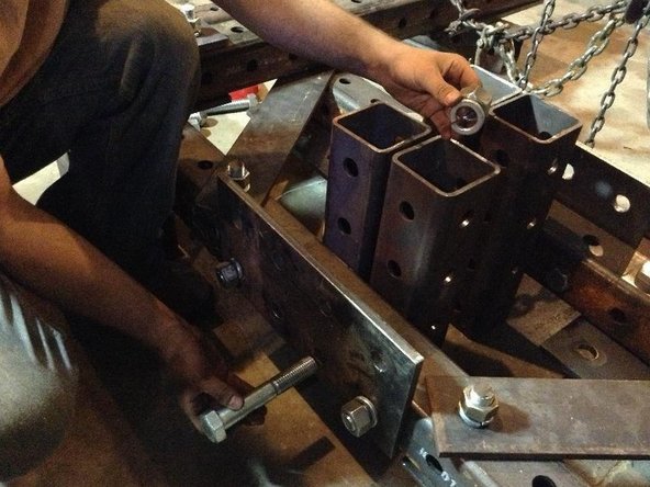
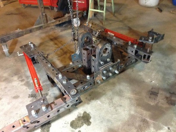
Take two 12-hole steel tubes. These will be used to mount the Quick Attach.
-
Mount two 3x1 hole plates on both ends of one 12-hole tube with 7" bolts and nuts. This will be the bottom of the Quick Attach plate.
-
Mount two 2x3 hole plates to the ends of the other 12-hole tube using 7" bolts and nuts. Use only the 2 inner holes, as the third hole will be used to mount the Stabilizer Legs.
-
-
-
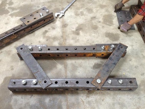
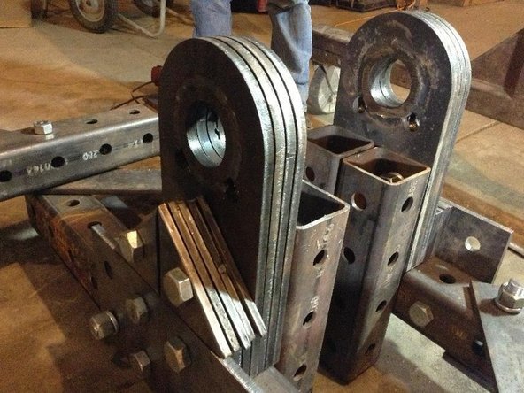
Build the Angled Support (pictured in step 3) from a 24" piece of 1/2"x4" plate. Punch 2 holes, 2" in from each end and at 20" spacing using a 1-1/16 bit in an open source Ironworker Machine.
-
These support pieces prevent side-to-side movement of the Quick Attach tubes.
-
-
-
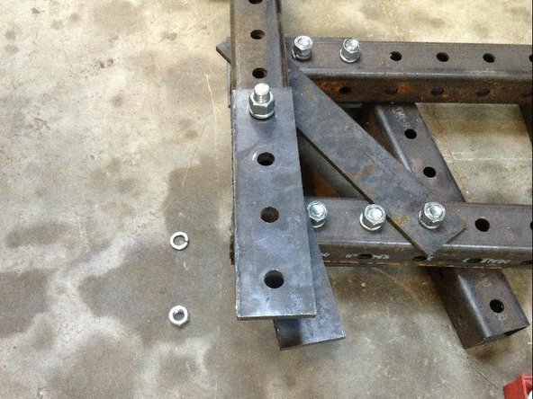
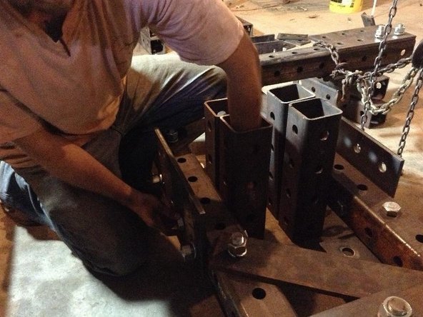
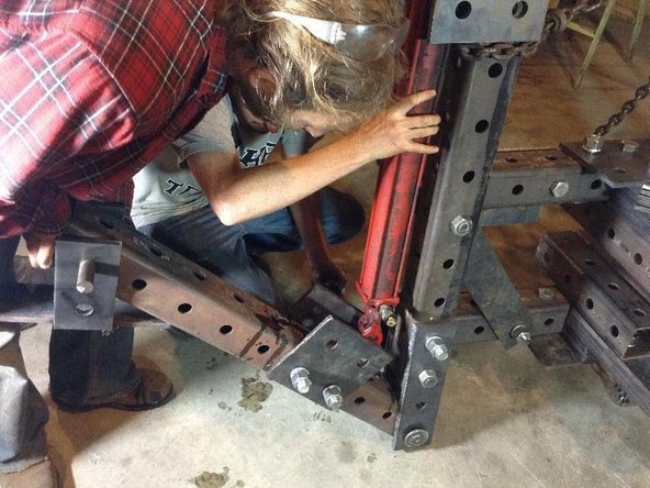
Install the 2 Angled Supports using 7 inch bolts, one on each side. (as pictured)
-
Note: there's a mistake in this picture! The 2 2-hole by 4-hole plates on the top tube should hang down instead of up.
-
-
-
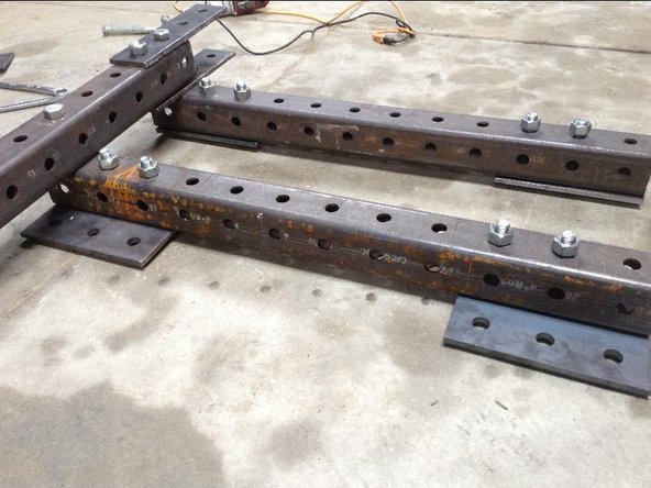
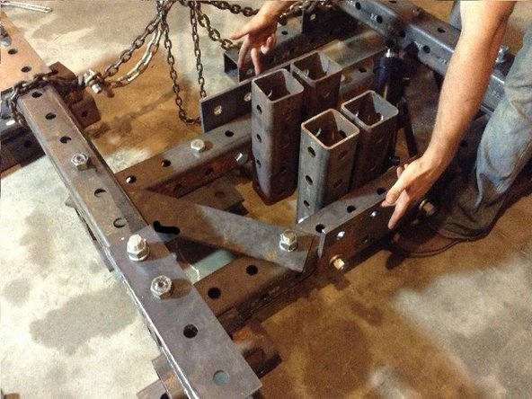
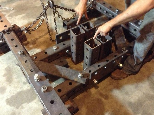
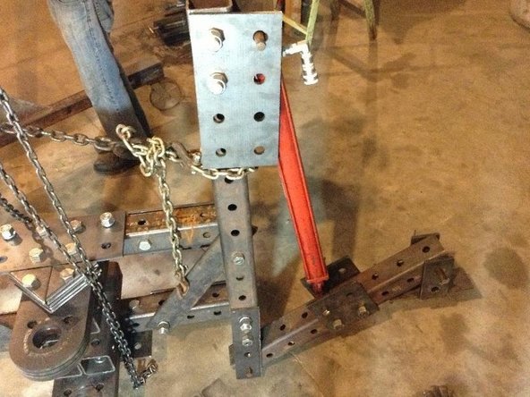
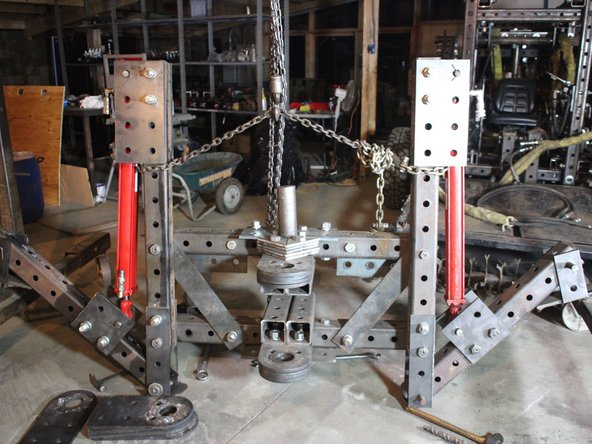
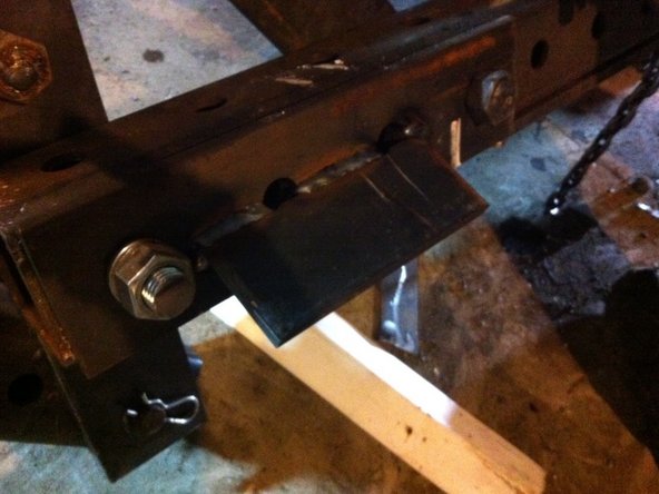
Mount two 4x1 hole plates to end of 12-hole tube to create vertical support for Stabilizer Legs. (RobK note - check length)
-
Attach using 7" bolts with two holes extended beyond the end of the 12-hole tube.
-
Mount these vertical supports to Quick Attach tube. Stabilizer Legs will attach to these. (note: photo inaccurate - angled support should already be in place).
-
Note: there's a mistake in this picture! The 2 2-hole by 4-hole plates on the bottom tube hangs off the wrong way. It should hang towards the other horizontal tube.
-
-
-
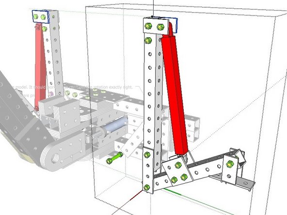
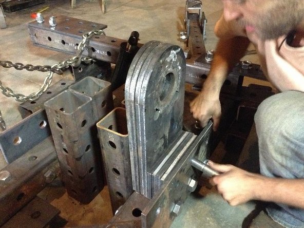
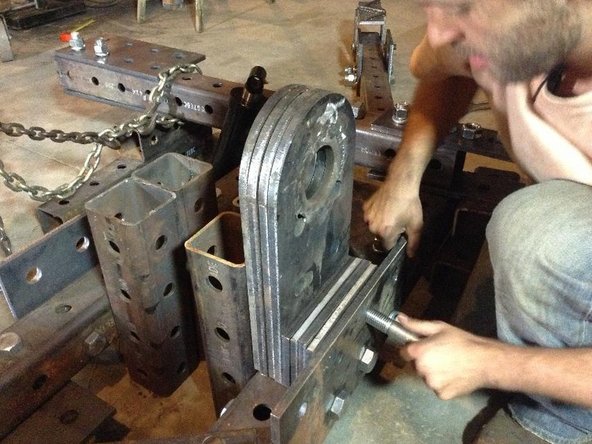
Install the Leg Pivot Plate (4x1 hole plate at bottom of image), only on the upper hole with 7 inch bolt.
-
-
-
Mount 2x1 hole plate at the top of each vertical leg stabilizer tube using a bolt to attach to the tube and a pin to the right of that, which the cylinder will rotate on.
-
Next attach a 2x2 hole plate to the 4th and 5th holes of the stabilizer legs.
-
Mount the Leg Cylinders to the plates at top and bottom using four 11" bolts.
-
-
-
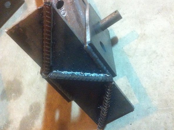
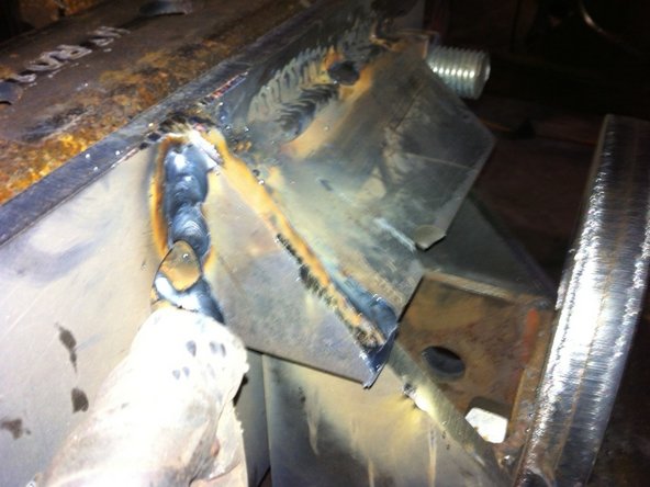
Weld feet to feet pivot plates (we used a stack of spacers to get the feet in the right position before tacking and welding).
-
Next weld a few pieces of something (we used small sections of rebar) to the bottom of the feet for added traction. We used a Z orientation with the hope that this would provide stability in several directions.
-
-
-
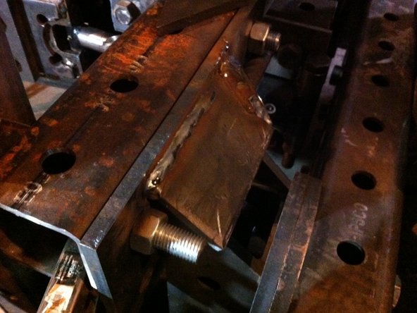
Attach two 2x4 hole Reinforcement Plates to the top and bottom Quick Attach tubes
-
-
-
Attach Main Pivot Tubes to Quick Attach tubes. Leave a space of 4" between them. Use ~10" bolts to attach Reinforcement plates to the Main Pivot Tubes (through Quick Attach tubes)
-
Insert bolts through the tube (bolts should not pass through the 4" space between the Main Pivot Tubes because the pivot cylinders will move through this space).
-
-
-
Attach 4 pivot plates and five 1x2 hole plates as spacers between Reinforcement plate and pivot tubes. Use ~6" bolts
-
Nuts will be mounted to the inside of pivot tubes. Hold the nut inside the tube (with a vice if necessary) while screwing in the bolts. Tighten with impact driver
-
-
-
Hold nut inside tube to do this.
-
-
-
Place Spacer Plates between the Bottom Reinforcement Plate and the Pivot Plates. Bolt these with 6" bolts
-
-
-
Bolt the Pivot Plates to the Main Pivot Tubes.
-
-
-
Step 18 wisdom
-
-
-
STep 19 ifo
-
-
-
Step 20
-
-
-
Step 21
-
-
-
Zero - flip pivot upside down using a hoist
-
-
-
build cylinder bottom mount plates consisting of one by four whole plate pieces
-
-
-
cut bushings four-cylinder bottom mount and bolt cylinder mount one by fours to the pivot part one
-
-
-
Cut 7.5 inch 1 inch shaft to size and weld a T handle on it consisting of a piece of 2" x 0.5" rebar
-
-
-
place cylinder in position and place shaft through Buesching and cylinder mount and through second Bushing
-
hold in place to where it will be welded put a small spacer underneath the rod and part of the cylinder to fit exactly within The 4 inch cavity of pivot part one.
-
The bushing location should be exactly 1.6 inches behind the & whole of the one by four hole plate, Or right behind the hole So that people can be put in the fourth hole of the one by four hole plate
-
-
-
Repeat for the second cylinder
-
-
-
Build cylinder rod and mount
-
-
-
take a 2 x 3 whole plate and notch out a space on the one and that is two and three-quarter inches from the edges and 2 inches deep.
-
-
-
Take a second plate which is an unfinished pivot plate and cut it down to 11 1/2 inches on the long side and cut off 1/2 inch from all sides to make it slightly smaller than the 3 x 2 whole plate
-
-
-
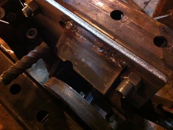
weld these two pieces together all around the edges for a solid fit.
-
-
-
Weld the 2 inch mounting bushings around the notch exactly 1.5 inches away from the edge of the 2 x 3 plate. Make sure that the spacing between them is exactly 2.25 inches or the width of the rod and cylinder tube. Weld with the shaft in place
-
-
-
weld the 2 x 3 gusset plate right in front of the cylinder mount bushings and weld solidly to the plate assembly. Do two of these per mounting plate.
-
-
-
repeat for the second cylinder
-
-
-
bolt the Rod and mount plate to pivot part two using short bolts. Do this only hand tight.
-
-
-
Put in the rod and mounting pin to make sure it fits
-
-
-
take off the Rob and mounting plate and put on two pivot plates. For mounting the boom
-
-
-
Bolt on the cylinder boom cylinder mounting assembly to the top of that part two
-
-
-
Mount the quick attach Finger assemblies on the tractor - at hole 10 on the front loader
-
Add spacer behind the assemblies so they clear bolts on pivot. (Extra pivot plates used as spacers in this build)
-
-
-
Move tractor to the backhoe and put the upper quick attach finger weldment into place on both the right and left-hand sides Of the quick attach and tack into place
-
Add triangular support to side of finger for strength
-
-
-
Add fingers for bottom of Quick Attach
-
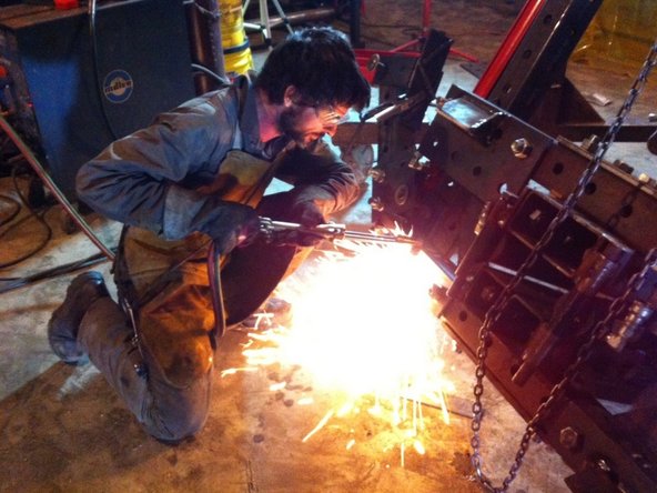
Determine the location of the latch hole for the bottom quick attach part and torch it out
-
-
-
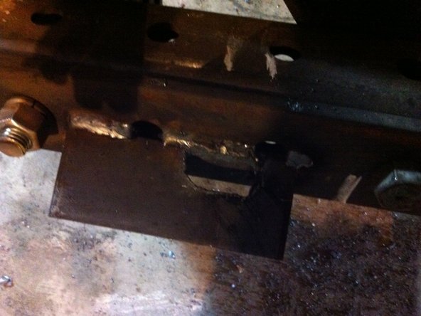
Put the bottom quick attach plate weldment into place on the backhoe and tack
-
-
-
Move tractor away and finish weld the quick attach plates on the Backhoe
-