
Difficulty
Moderate
Steps
13
Time Required
02:00:00 - 03:00:00
- Contructing the Backhoe Bucket 13 steps

In Progress
This guide is currently being written. Reload periodically to see the latest changes.
Quiz
0
Introduction
All plates are 1/2" low carbon steel plates type ASTM A36 or similar.
Tools
Parts
- 17"x23-11/16"x1/2" steel plate (bucket side plate - left)
- 17"x23-11/16"x1/2" steel plate (bucket side plate - right)
- 16"x16"x1/2" steel plate (bucket bottom)
- 4"x16"x1/2" steel plate (bucket top)
- 8"x16"x1/2" steel plate (bucket back-1)
- 8"x16x1/2" staal plate (bucket back-2)
- 8"x16"x1/2" steel plate (bucket back-3)
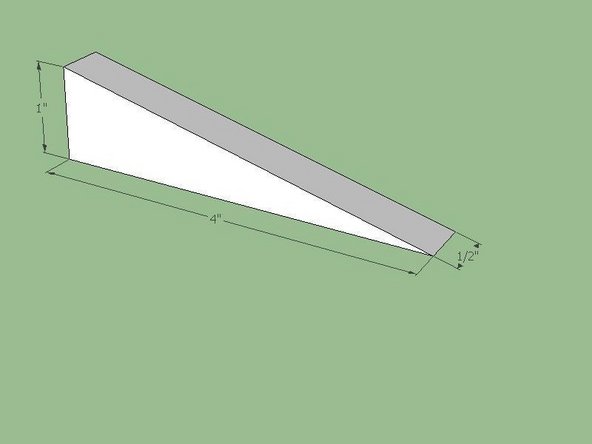
- 4"x6"x1/2" steel plate (bucket teeth)
- 16"x2-1/2"x2-1/2"x1/2" steel angle (tooth adapter)
-
-
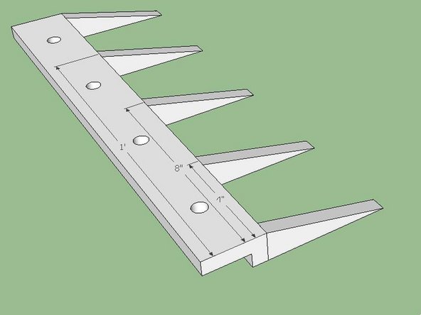
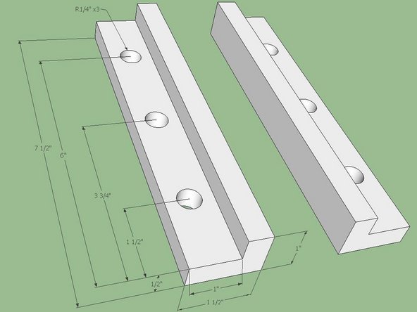
Start with two plates cut according to the dimensions in the Fig. The large piece in the center is called a “Bucket Side Plate”. Two are required to complete the Bucket. The two smaller triangles at the bottom were designed to be 30/60/90 triangles. The 30/60/90 triangles should control/drive the linear dimensions.
-
-
-
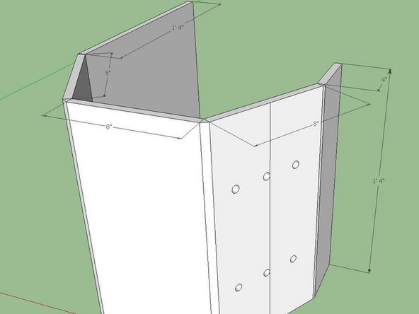
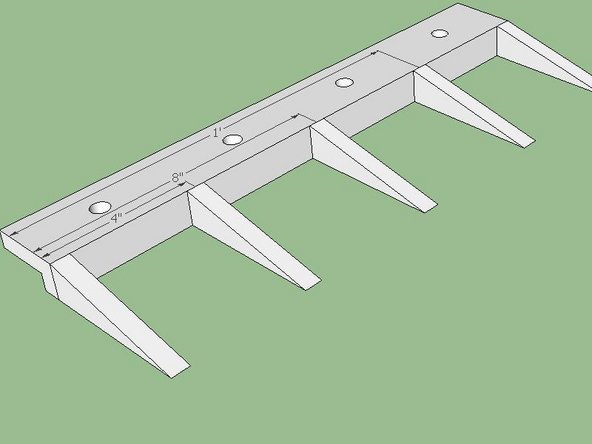
Acquire two ½” thick steel plates that are 8”x16”, one plate that is 4”x16”, and one plate that is a 16” square.
-
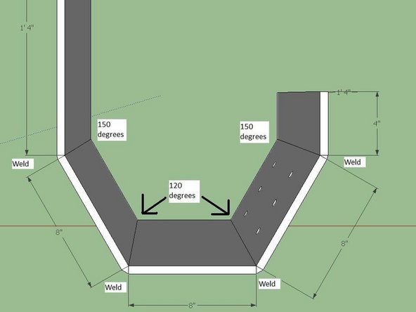
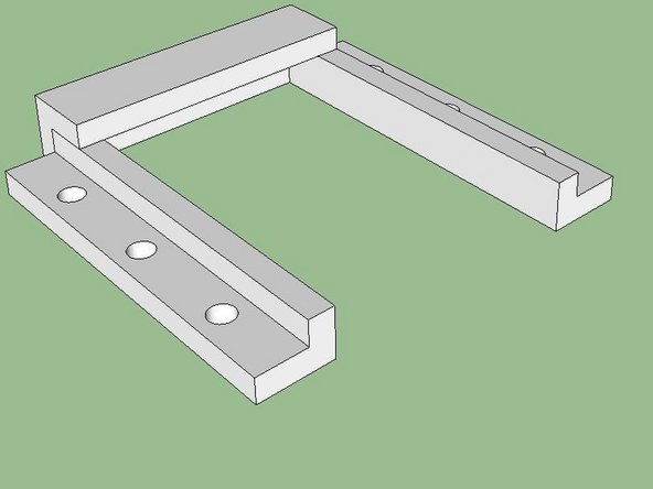
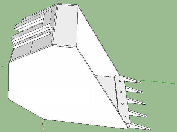
The plates will be welded together as shown in the Figs. below. The angles of the plates are symmetrical.
-
From the square plate to the adjacent plate (the plate without holes) the angle is 150 degrees. From the 4” plate to its adjacent plate (the plate with holes) is also 150 degrees. From the remaining 8”x16” plate to the two adjacent plates the two angles are 120 degrees.
-
The plate with the holes must be oriented properly. The side with of the plate with two holes must be attached to the 8” plate. The side of the plate with one hole must be attached to the 4” plate.
-
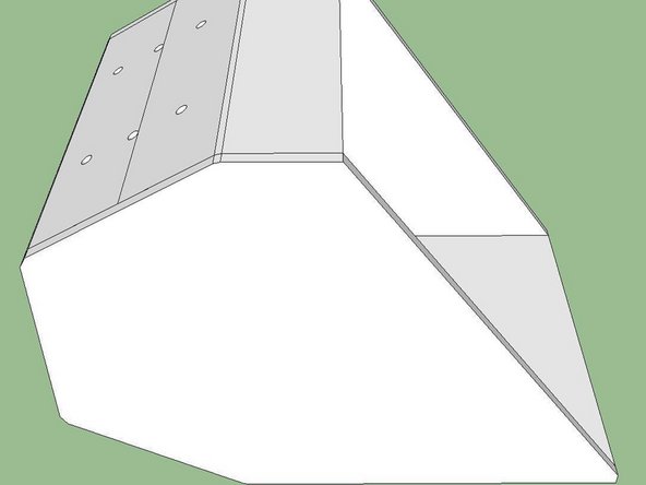
Once all the plates are welded together the component is called the “Bucket Body”.
-
-
-
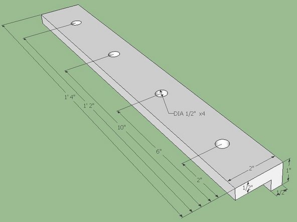
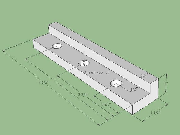
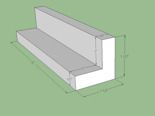
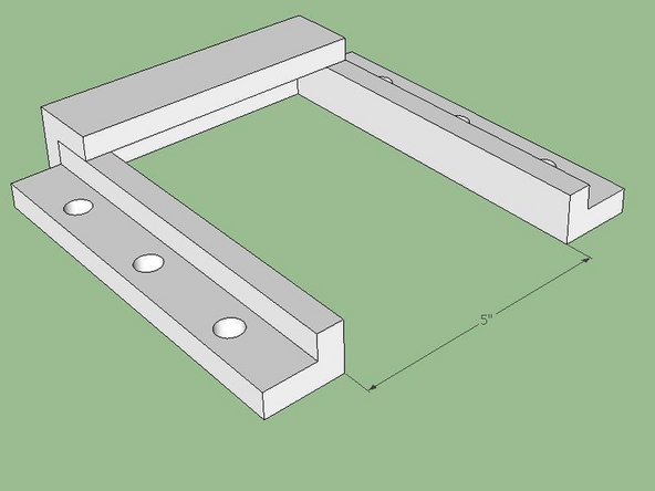
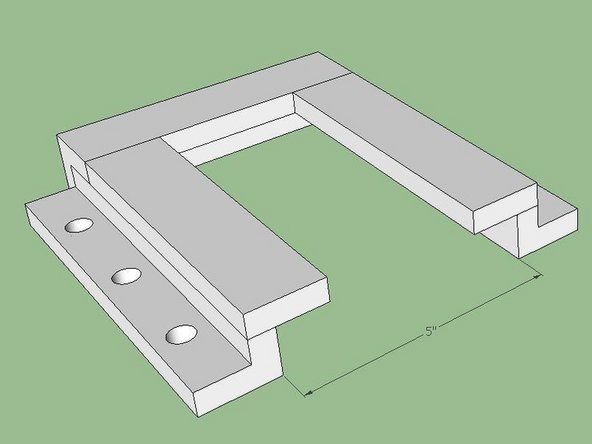
Assemble the brackets as shown and weld together.
-
The interior must be square. Avoid welding the interior joints. If welding of the interior joints is necessary then be sure to grind down the interior surfaces to be flat and square.
-
The 5 inch dimension is minimum clearance. For easy insertion and removal a tolerance should be included. Any tolerance built in would affect Step 2 and Step 9.
-


Cancel: I did not complete this guide.
One other person completed this guide.