Difficulty
Moderate
Steps
7
Time Required
- TAZ Final 7 steps

In Progress
This guide is currently being written. Reload periodically to see the latest changes.
Quiz
0
Tools
Parts
- Frame Assembly XZ
- Y axis assembly
- Motor extension -1
- Motor extension -2
- Motor extension -3
- Motor extension -4
- Extruder extension
- X switch extension
- Y switch extension
- Z switch extension
- Heat bed extension
- Strain relief plate
- Strain relief outer
- Corrugated tubing 100mm
- Rubber feet
- Small Zip ties
- M3 x 6 set screw
- M3 x 12 SHCS
- M3 Washer
- Thumb screws
- Heat Bed
-
-
GATHER PARTS FOR THE FINAL ASSEMBLY
-
TL-FX0006 Fixture
-
TL-FX0018
-
TL-FX0017
-
-
-
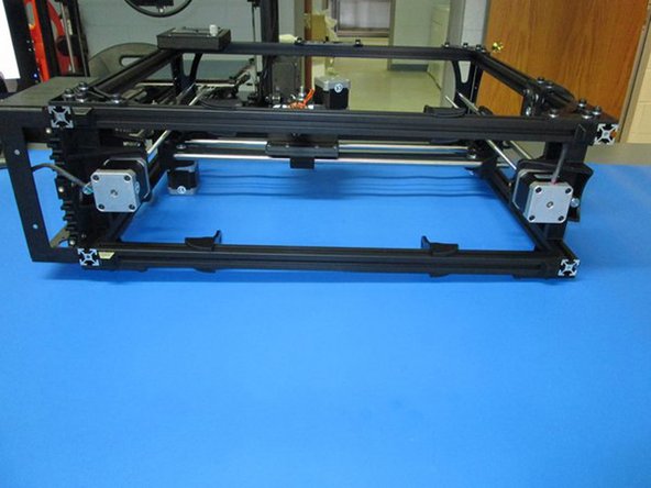
ADD FEET TO THE FRAME ASSEMBLY
-
Install 4x rubber feet to bottom of frame.
-
-
-
ADD FEET TO FRAME ASSEMBLY (continued)
-
Take note of location, do not cover bottom of vertical extrusion.
-
All four feet shown
-
-
-
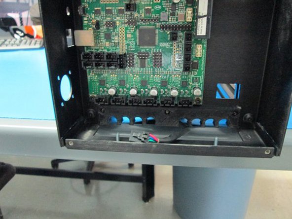
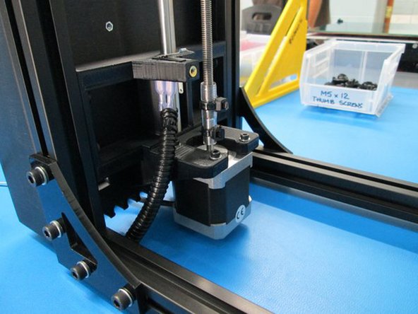
PLUG IN Z LEFT MOTOR
-
Route Z left motor wire through relief position #5.
-
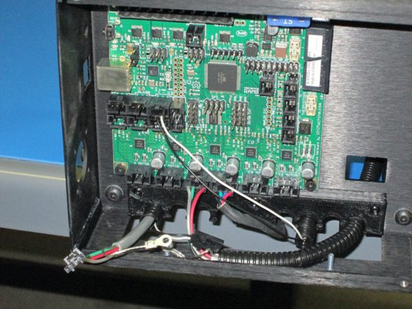
Plug into the board in location shown.
-
Photo 1 - Route Z left motor wire through relief #5
-
Photo 2 - Plug motor into RAMBo board in this location
-
-
-
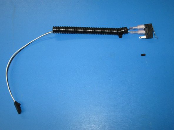
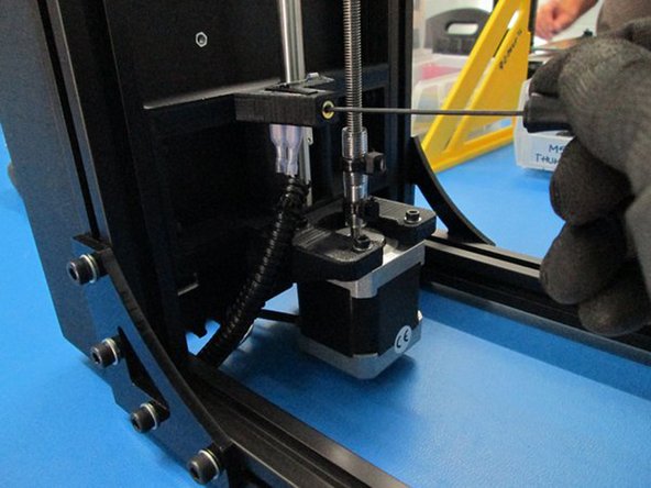
INSTALL THE Z SWITCH
-
Install switch as shown and secure with a M3 x 6 set screw.
-
Route wires through relief #6 and plug in as shown.
-
Photo 1 - Limit switch parts
-
Photo 2 - Install switch into Z motor mount left
-
Photo 3 - Secure with set screw
-
-
-
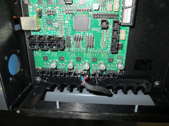
INSTALL THE Z SWITCH (continued)
-
Route wires through relief #6 and plug in as shown.
-
Plug in as shown
-
-
-
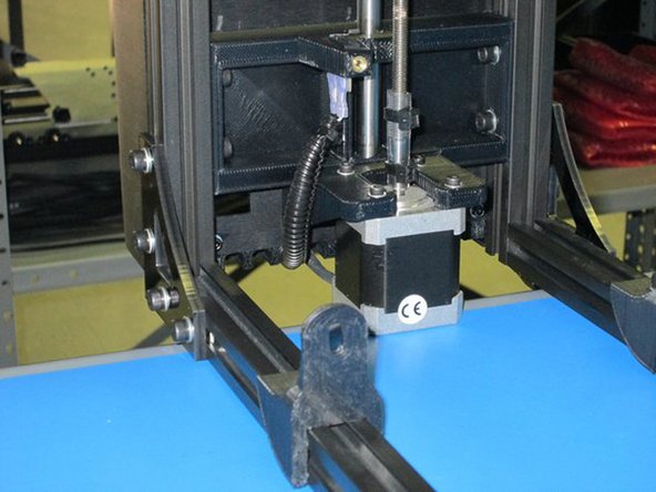
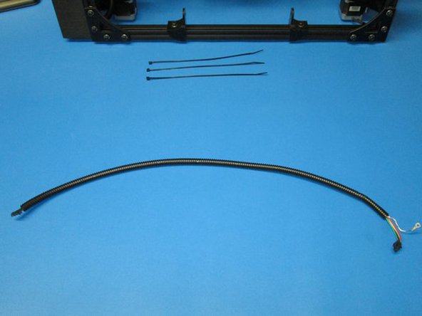
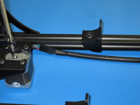
ADD THE Z RIGHT MOTOR EXTENSION
-
Connect the Z motor extension to the right Z motor.
-
Route the extension through relief position #8.
-
Plug in as shown and put ground lug on post.
-
Zip tie at the 3 locations indicated while removing slack.
-
Photo 1 - Z motor right extension parts
-
Photo 2 - Plug extension into Motor
-