-
-
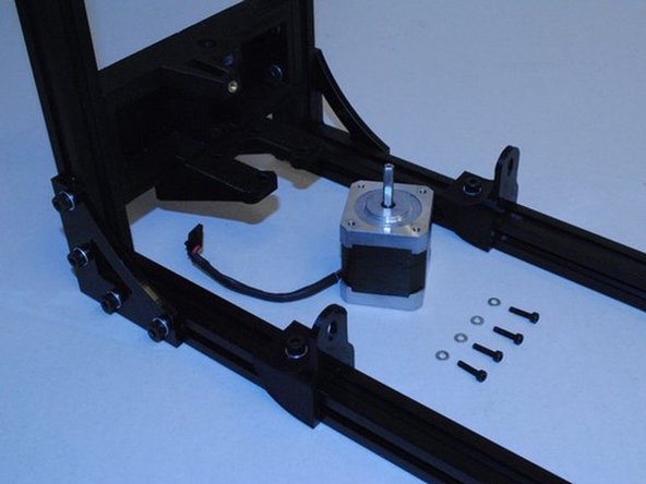
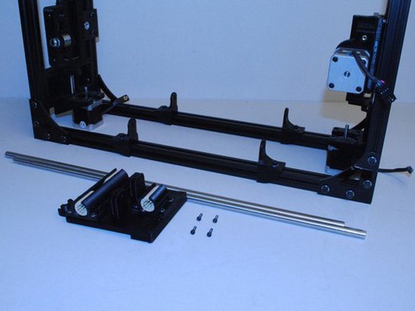
GATHER PARTS FOR FRAME XZ ASSEMBLY
-
3mm Allen Driver
-
Side Cutter
-
Zip Tie Gun
-
1.5mm Allen Driver 2.5mm Allen Driver 4mm Allen Driver
-
-
-
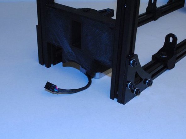
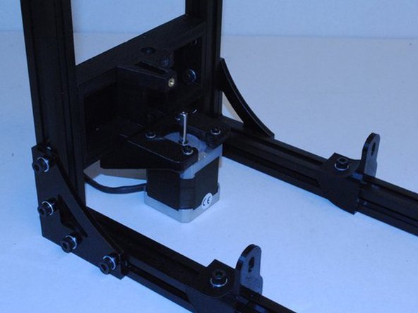
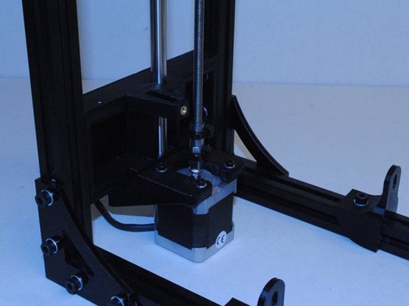
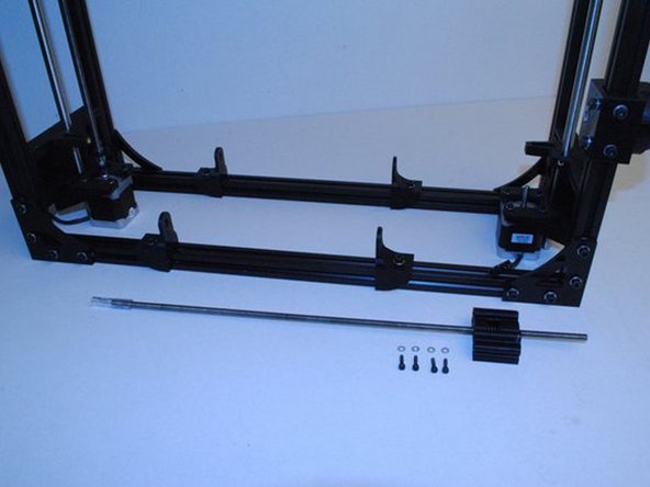
INSTALL SMOOTH ROD AND X END MOTOR
-
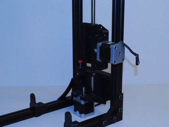
Slide a 10mm smooth rod up through the bottom of the left Z motor mount.
-
Once you get it started, put the X end motor onto the 10mm rod.
-
Slide the rod in until the end is flush with the top of the Z top flat plate.
-
Use a M3 x 6 set screw to secure the rod in place.
-
-
-
INSTALL SMOOTH ROD AND X END IDLER
-
Slide a 10mm smooth rod up through the bottom of the right Z motor mount.
-
Once you get it started, put the X end idler onto the 10mm rod.
-
Slide the rod in until the end is flush with the top of the Z top flat plate.
-
Use a M3 x 6 set screw to secure the rod in place.
-
-
-
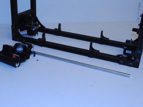
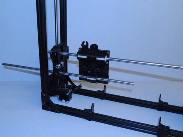
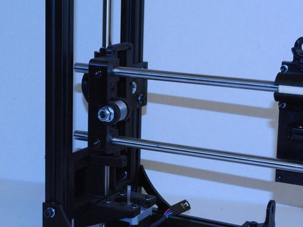
INSTALL X CARRIAGE AND GUIDING RODS
-
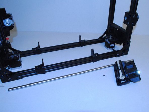
Slide a 10mm rod through one of the two holes in the X end idler.
-
Once its through far enough, put the X carriage on the rod.
-
Finish sliding the 10mm rod through until it's also inserted into the X end motor.
-
The rod will be flush with the outside of the X end motor.
-
Repeat with the second 10mm rod in the second set of holes.
-
-
-
INSTALL X CARRIAGE AND GUIDING RODS (continued)
-
Using 4 M3 x 12 SHCS, lock the rods in place at the X ends.
-
Tighten the bolts holding the bearing holders on the X carriage making sure it still slides freely back and forth.
-
Tighten the bolts holding the double bearing holders on the X ends at this point as well.
-
Does the x carriage slide smoothly back and fourth?
-
Did you tighten all the bearing holder bolts?
-
-
-
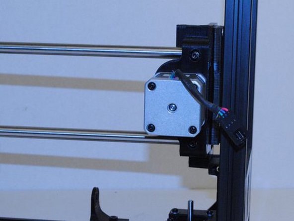
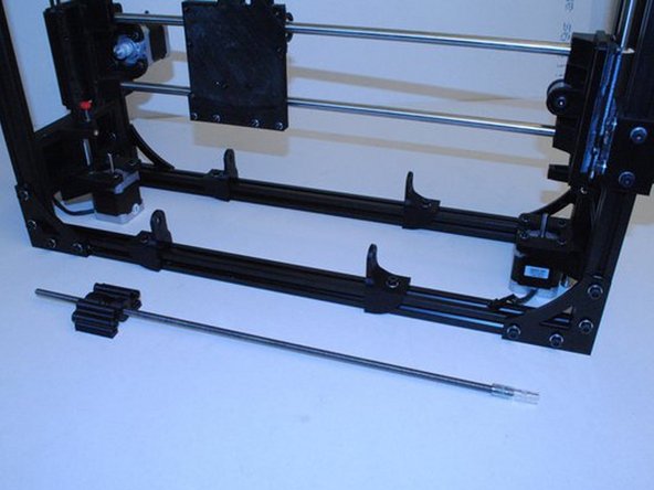
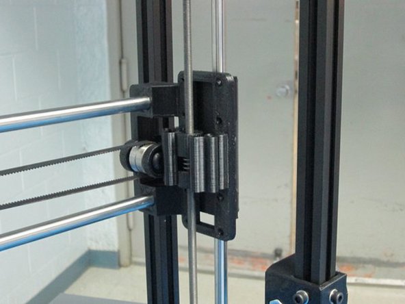
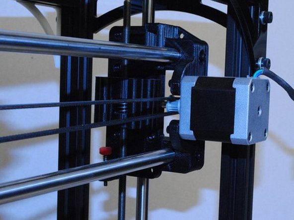
INSTALL LEFT DRIVE ROD
-
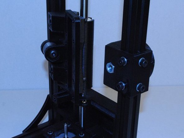
Push the end of the coupler tube down onto the Motor shaft.
-
Lift up the X/Z axis until you can bolt the Z nut holder to the X end motor.
-
Using 4x M3 x 12 SHCS and M3 Washers, attach the Z nut holder to the X end motor.
-
Install large zip ties on the end of the drive rod and on the motor shaft as shown.
-
he zip does must be tight enough that you can't pull the drive rod off vertically.
-
Did you pull up on the drive rod to check the zip ties?
-
-
-
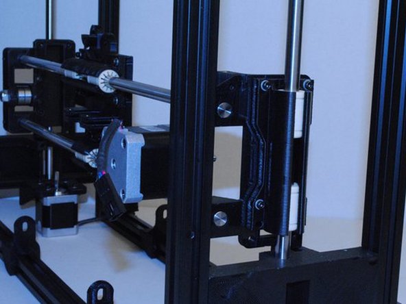
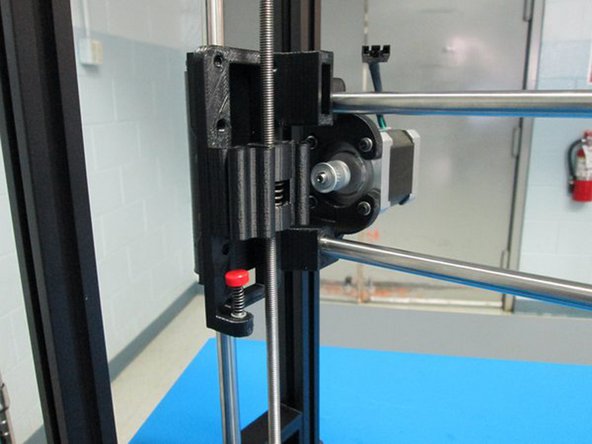
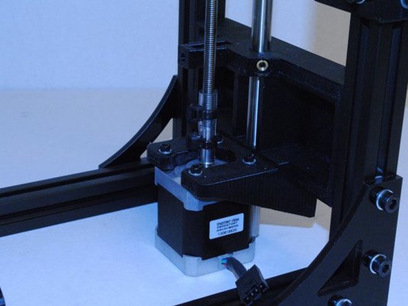
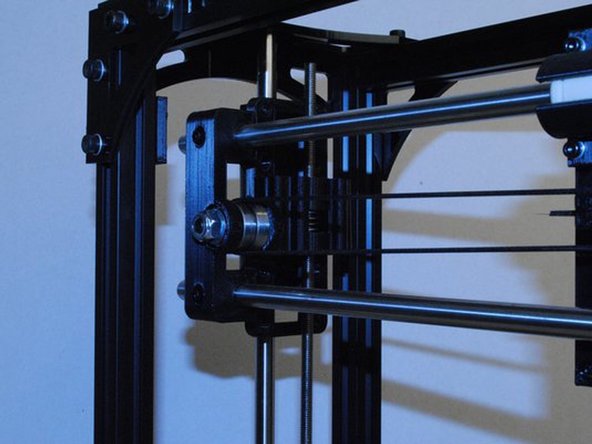
INSTALL RIGHT DRIVE ROD
-
Push the end of the coupler tube down onto the Motor shaft.
-
Adjust the height of the Z nut holder by spinning it to get it close in height to the X end idler.
-
Using 4x M3 x 12 SHCS and M3 Washers, attach the Z nut holder to the X end idler.
-
Install large zip ties on the end of the drive rod and on the motor shaft as shown.
-
The zip must be tight enough that you can't pull the drive rod off vertically.
-
Did you pull up on the drive rod to check the zip ties?
-
-
-
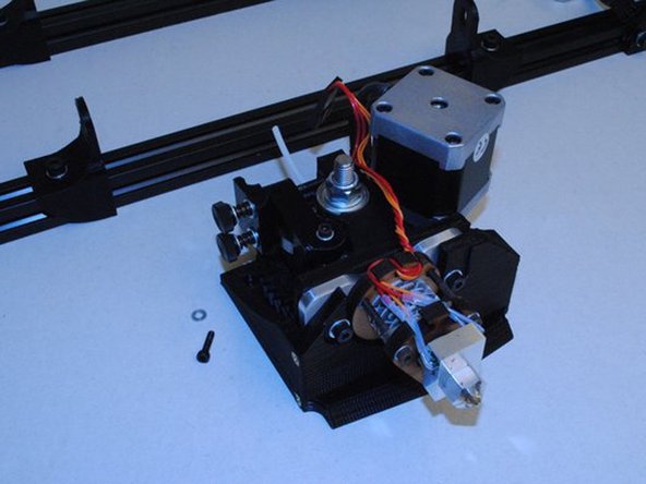
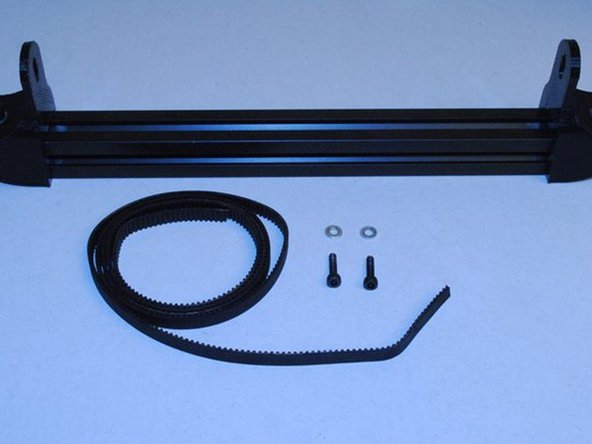
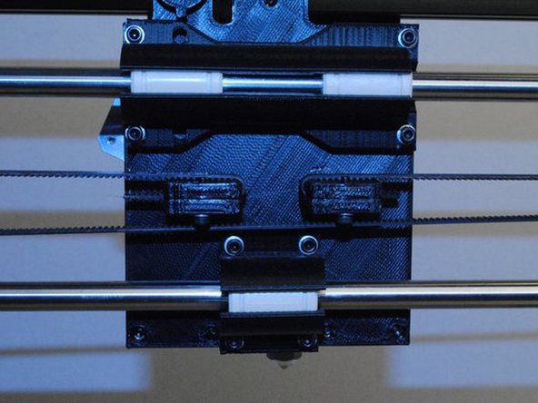
INSTALL THE X BELT
-
First cut the belt with a side cutters.
-
Route one end through the X carriage as shown and clamp down with a M3 x 12 SHCS and M3 Washer.
-
Next route the belt around the pulley on the X end motor and the bearings on the X end idler.
-
Finish routing the belt back at the X carriage.
-
-
-
INSTALL THE X BELT (continued)
-
Pull tight and clamp down with a M3 x 12 SHCS and M3 Washer.
-
Trim the ends of the belt so they do not interfere with the pulley or bearings.
-
Check for belt rubbing as you move the X carriage back and fourth. Adjust as necessary.
-
Is the belt nice and tight?
-
Does the belt rub anywhere?
-
-
-
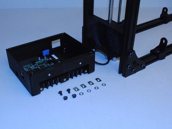
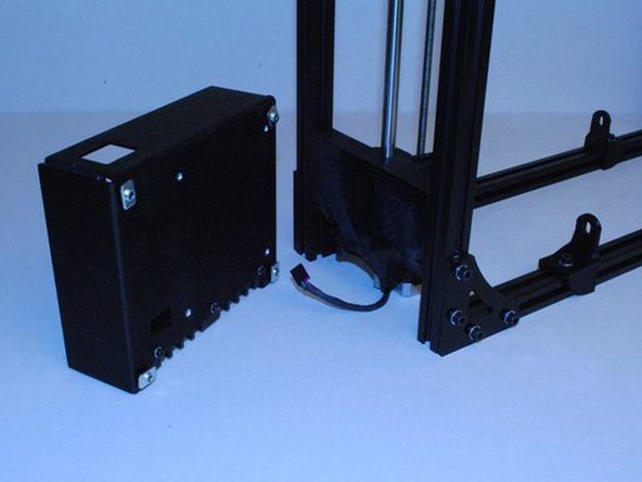
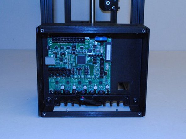
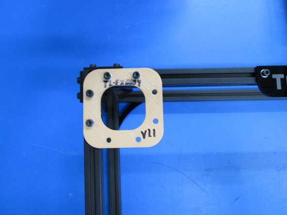
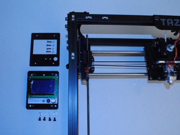
INSTALL THE LCD CASE ASSEMBLY WITH COVER (not this model)
-
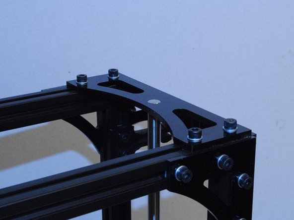
Remove the assembly fixture TL-FX9999 from the corner of the frame.
-
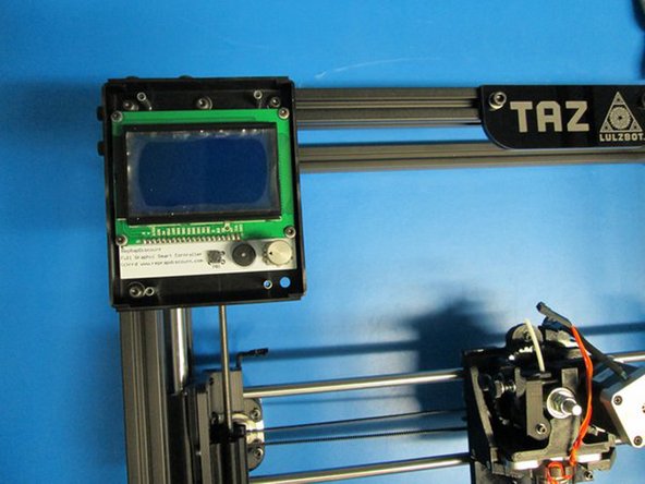
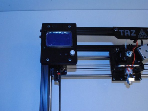
Using the already installed M5 T-nuts along with 4x M5 x 8 BHCS and M5 Washers, attach the LCD case assembly to the frame.
-
Set the edge and top of the LCD case flush with the outside of the frame.
-