-
-
Review Free CAD image
-
-
-
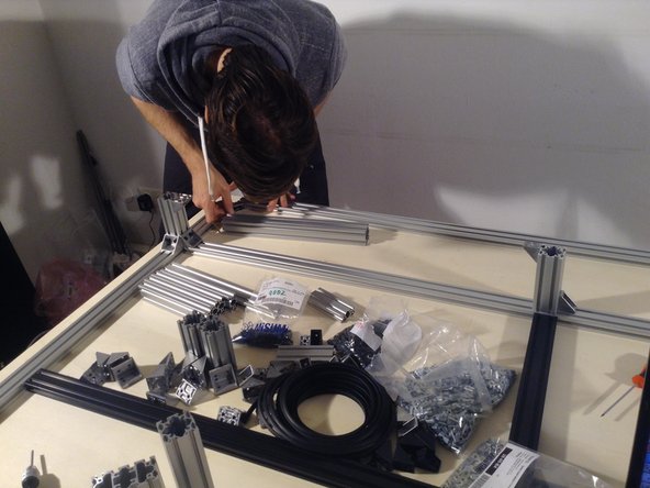
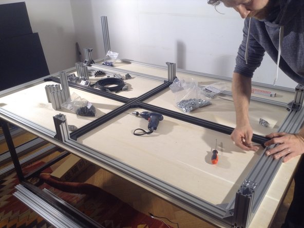
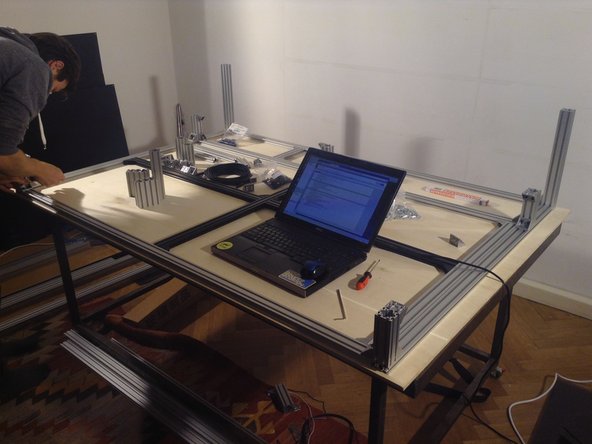
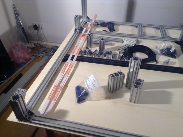
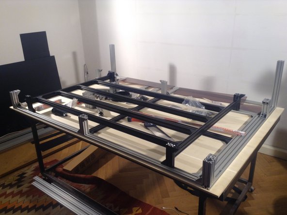
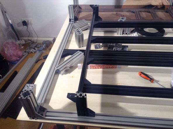
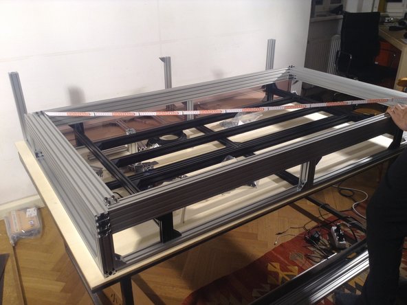
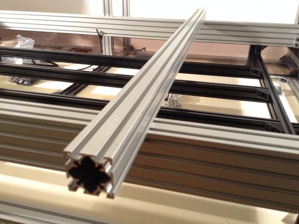
Lay out materials for outer frame from http://labs.nortd.com/lasersaur/bom-subs...
-
-
-
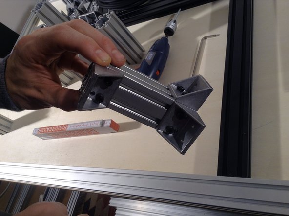
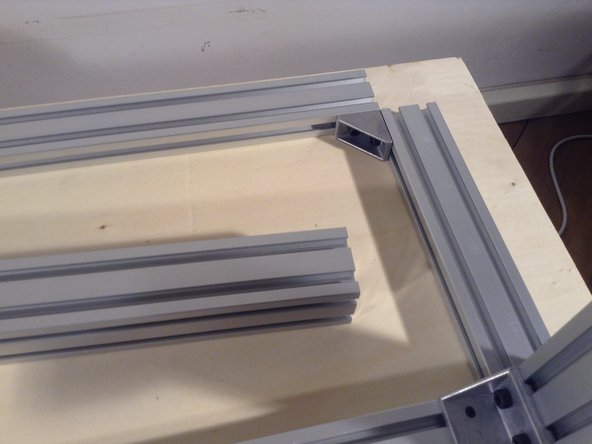
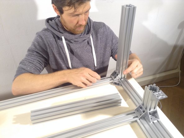
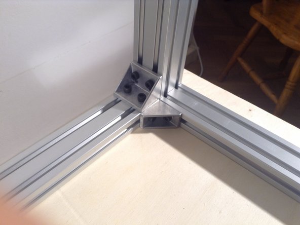
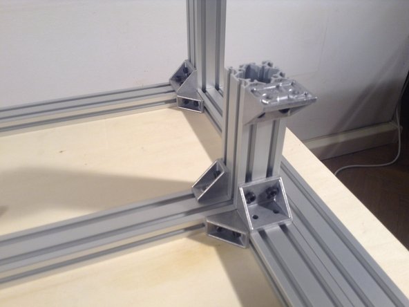
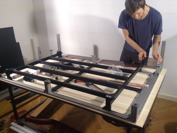
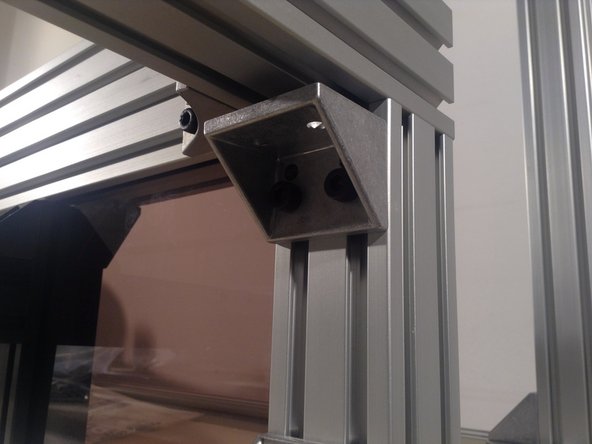
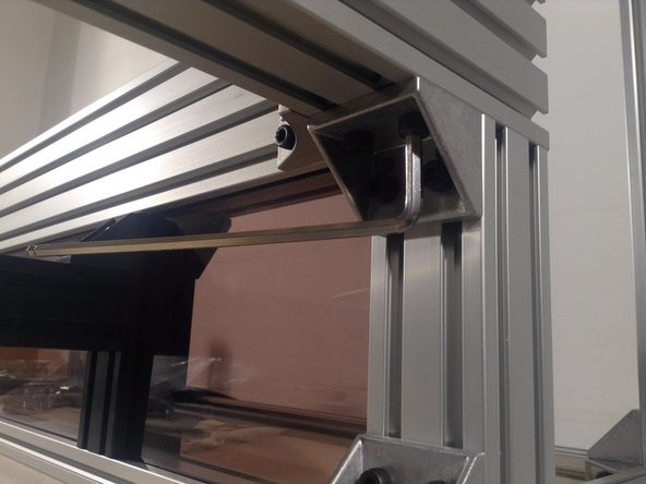
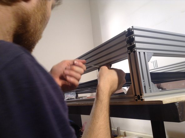
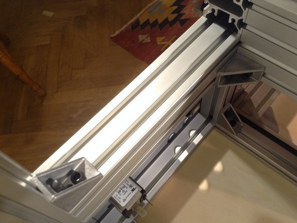
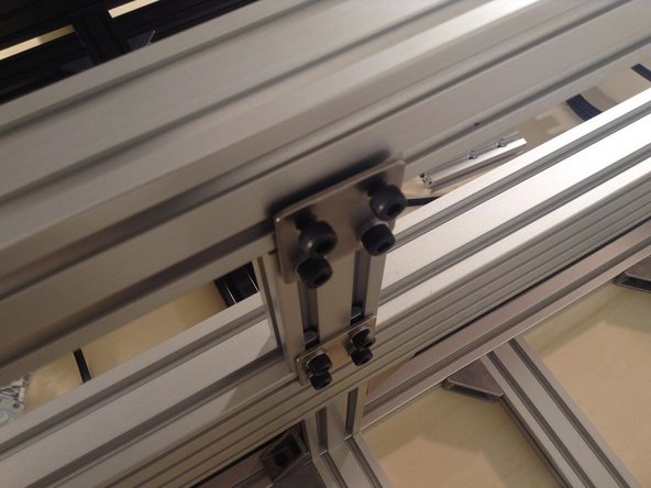
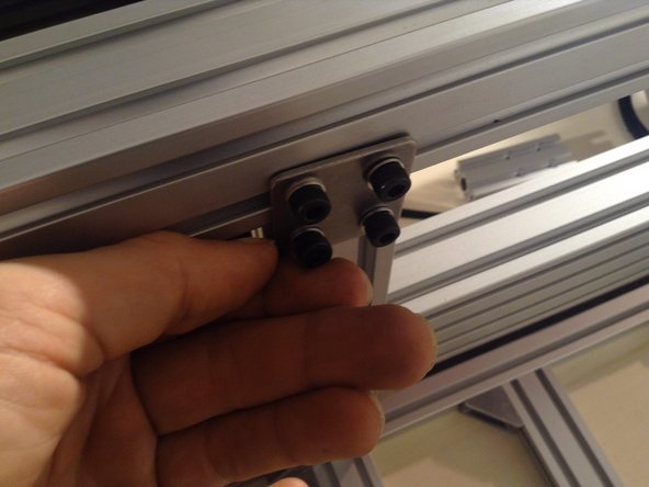
Preassemble corner pieces, 2 mirror images Use 3 double brackets. Until the very end, leave all connections loose.
-
-
-
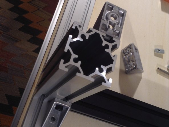
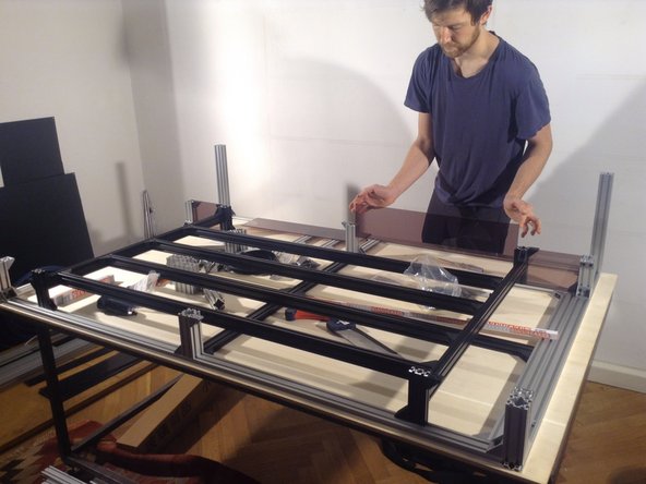
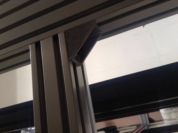
Build second corner bracket for front of frame
-
-
-
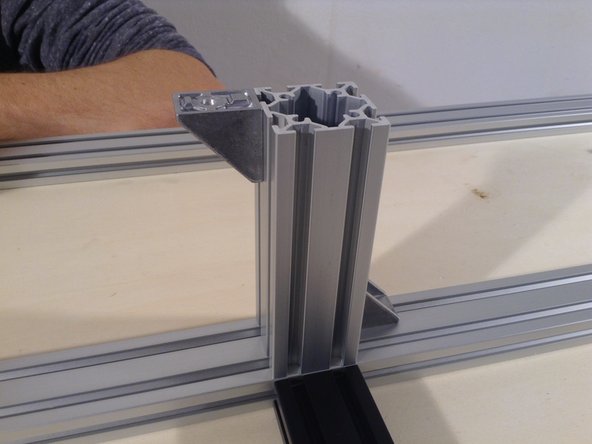
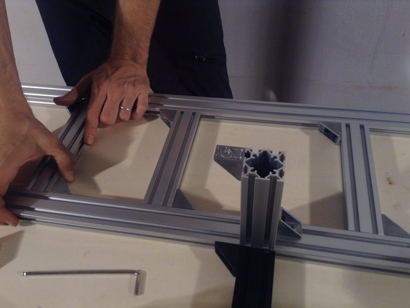
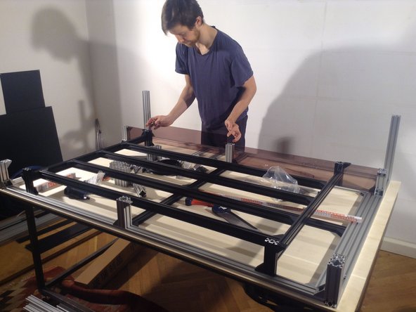
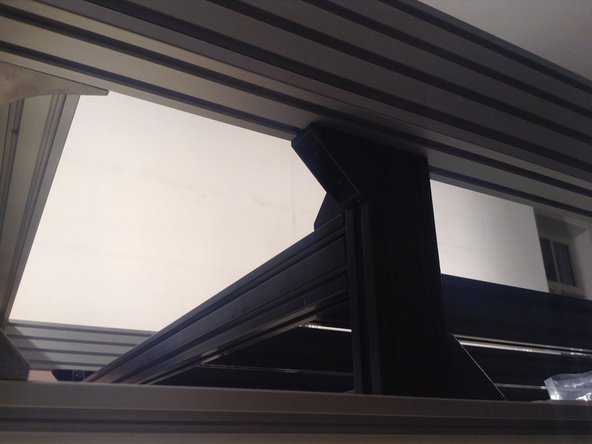
Build middle vertical column, front, use 2 brackets.
-
-
-
Build middle rear vertical column.
-
-
-
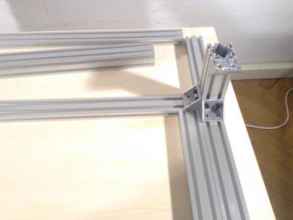
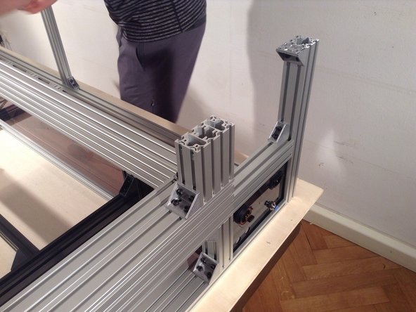
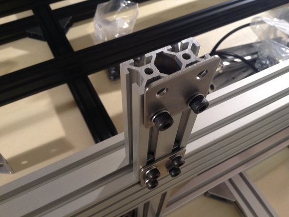
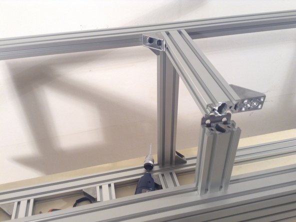
Build rear 3rd corner vertical. Use 2 double and one single bracket. (note later time)
-
-
-
Build 4th rear corner vertical. (second pix at same time as last)
-
-
-
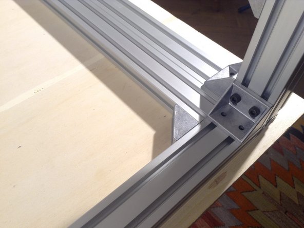
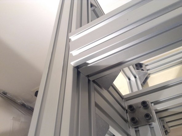
Build rear corner horizontal using a single bracket.
-
-
-
Do the same on the rear left corner.
-
-
-
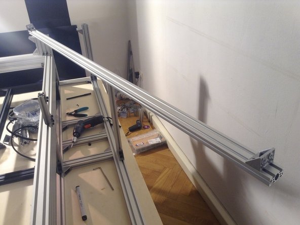
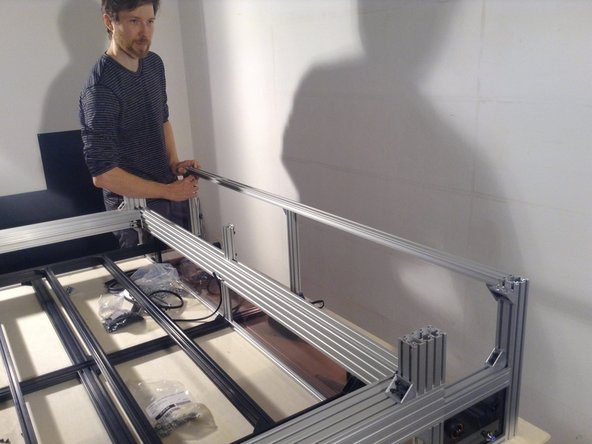
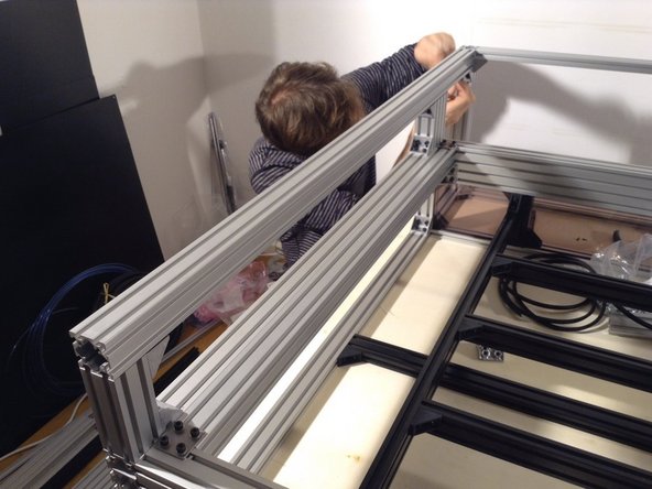
Install rear vertical of overall frame
-
-
-
Install single bracket for rear left vertical, and rear right vertical.
-
-
-
Install single bracket on right front cutting chamber horizontals.
-
-
-
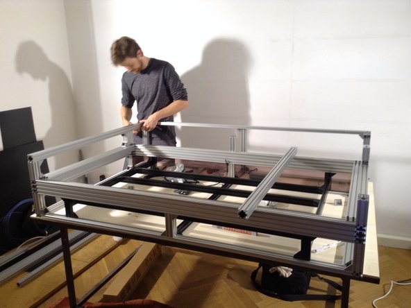
Install middle black supports on the floor of the frame, using single black brackets, 1 per meeting point
-
-
-
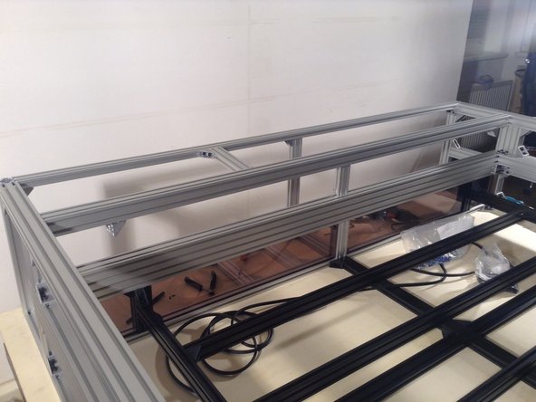
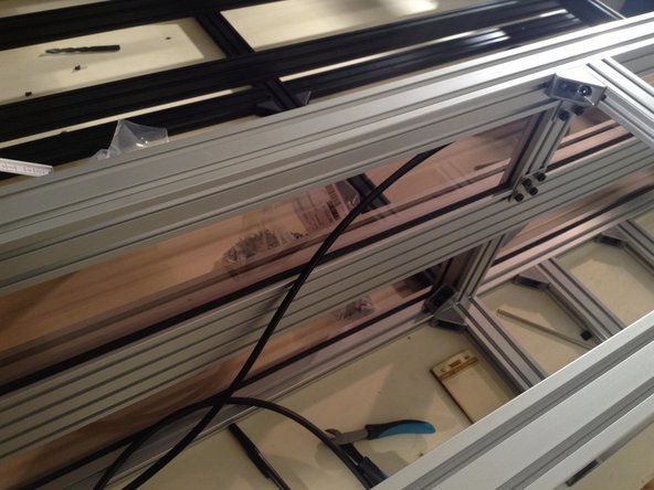
Install 3 short 2040 extrusions on the rear base of the frame.
-
-
-
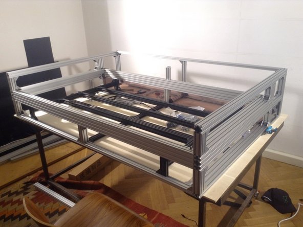
Tighten down all joints. Insert spring nuts as needed.
-
-
-
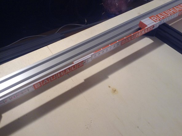
Inner distance between extrusions for the front compartment should be 86 cm.
-
-
-
Space between front horizontal and mid horizontal should be 41 cm on the inside.
-
-
-
Use the small polycarbonate separation panel - mark a .6x.6 cm corner cut out.
-
-
-
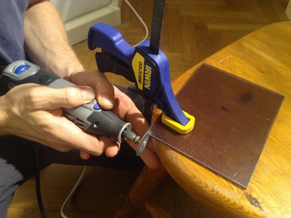
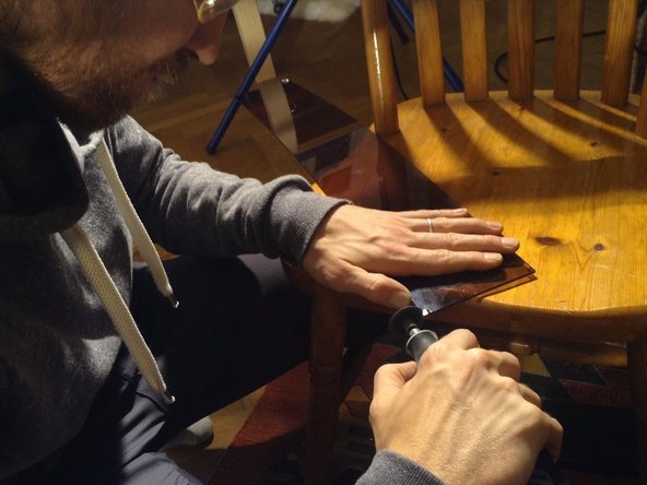
Cut the corner out with a dremel tool. The corner cutout allows the panel to fit against the walls of the frame.
-
-
-
Do the same for the second of the same panel.
-
-
-
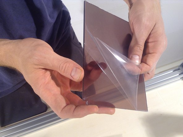
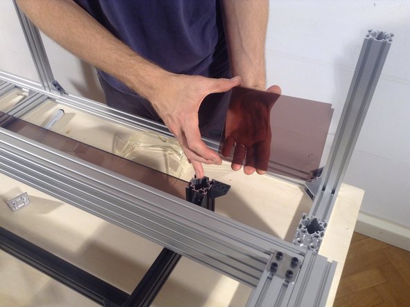
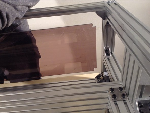
Peel the protective covering from the small panel, and insert.
-
-
-
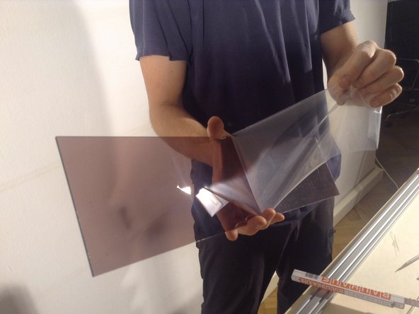
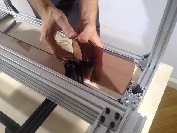
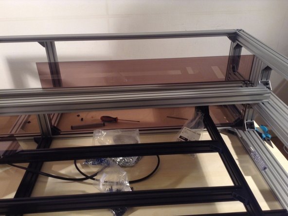
Peel the protective covering from the long panel, and insert.
-
-
-
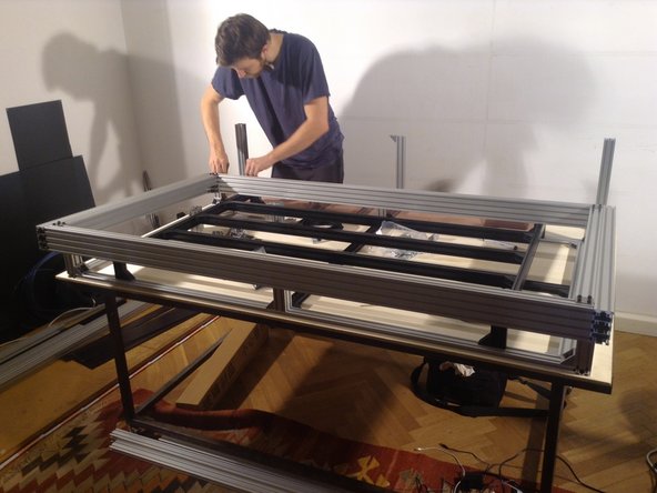
Take out the panels, insert the table frame.
-
-
-
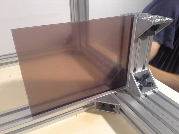
Insert the small separation panels
-
-
-
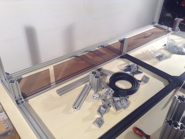
Insert the large separation panels
-
-
-
Measure for parallel of the front and back. Also measure the diagonals to check that they are within 2 mm.
-
-
-
Mount the base brackets of table to the outer frame - both for the front and back side of the table.
-
-
-
CHECK Mount the middle rear vertical to the outer frame.
-
-
-
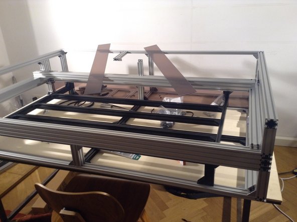
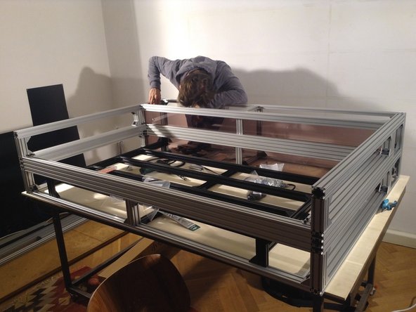
Place the gantry frame on top of the table.
-
-
-
Cut out the upper corner of the small separation panel, for both panels.
-
-
-
Place the separation panels in the frame.
-
-
-
Measure the diagonal of the gantry frame to see that it's square.
-
-
-
xxxThen tighten down the 3 more single brackets in the front and in the rear.
-
Tighten down the gantry frame to the bottom outer frame. Start with the 4 corners.
-
-
-
Tighten down the gantry frame to the bottom outer frame. Start with the 4 corners.
-
-
-
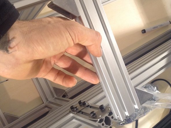
Cut rubber gasket to size for the long separator windows - 2 seams on top and bottom horizontals. See example of how the rubber gasket fits in the grooves of the aluminum extrusion.
-
-
-
Insert rubber gasket in the bottom window edge. Poke in with the blunt end of a pen or some other object that helps the rubber to be pushed in the groove to create a tight seal.
-
-
-
Insert rubber gasket in the top window edge.
-
-
-
Insert small vertical support, a 4080 extrusion - rear post for the door.
-
-
-
Start with the spring nuts
-
-
-
Put in bracket and 2 screws.
-
-
-
Put in 2 remaining screws. Repeat for the second vertical support.
-
-
-
Continue to the 4040 extrusion for the front post of the door.
-
-
-
(These steps should be done before corner post being put in)
-
Take off protective foil from External Connection Panel.
-
-
-
Take out corner post.
-
-
-
Mount corner post, after putting in the panel.
-
-
-
Mount the 2 front corner posts on top of the gantry frame.
-
-
-
Mount the middle rear support on top of the gantry frame, using a flat bracket (10:43)
-
-
-
Mount side extrusion above the External Connection Panel, using 2 single brackets.
-
-
-
Mount double brackket on top of 2 corner posts.
-
-
-
Mount top flat bracket on top of middle rear surrport above the gantry frame.
-
-
-
Mount rear horizontal, 2040 extrusion with 2 double brackets, and then mount the midpoint with a single bracket.
-
-
-
Mount the side 4040 extrusions.
-
-
-
Side 4040 extrusions done.
-
-
-
Mount 2040 extrusion - the mid support at the rear of the frame.
-
-
-
Mount 4040 extrusion for the rear of the cutting chamber - using 2 double brackets at the sides and a double planar bracket in the middle.
-
-
-
Use small bolts (8 mm long) and a washer for the flat double bracket. Before fixing this rear post in place, we need to install the back separator window.
-
-
-
Take the rear window and peel the protective cover.
-
-
-
Cut edges out with a dremel tool.
-
-
-
Install on the right hand side.
-
-
-
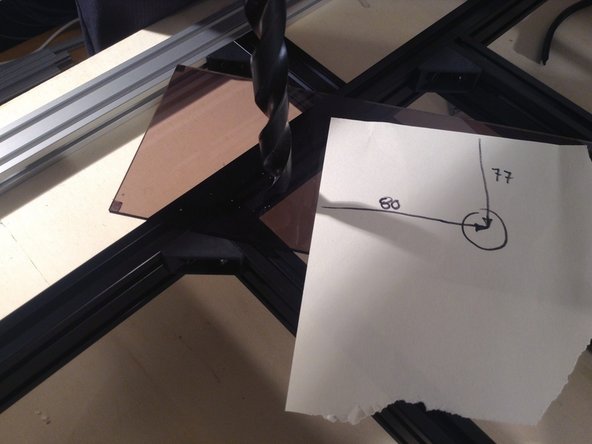
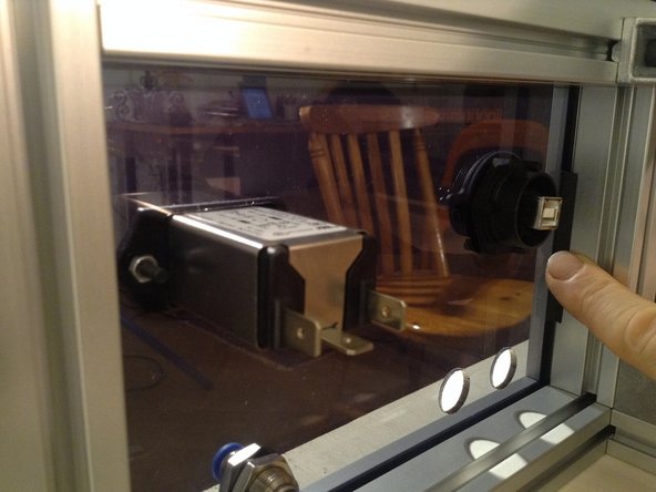
For the second panel, cut edges with dremel tool and then drill out a 16 mm hole, in location as shown.
-
-
-
Put in upper rear windows and close off with 4040 extrusion on top.
-
-
-
Cut rubber gaskets and put them in the side external connection window.
-
-
-
Finish putting in rubber gaskets - on the 2 horizontals in each window - for the 2 upper windows.
-