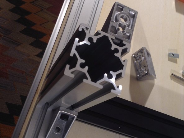
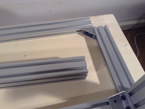
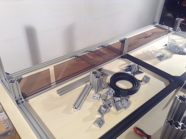
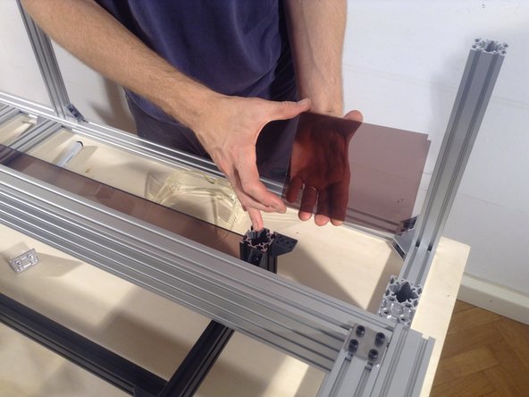
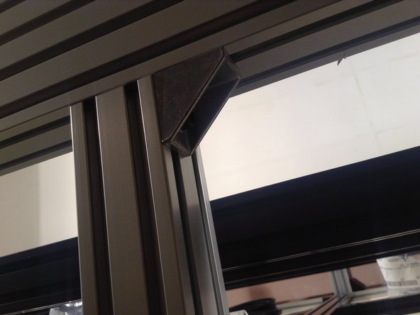
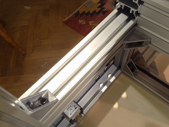
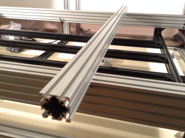
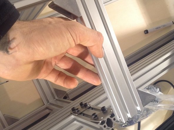
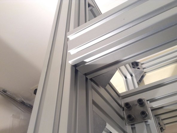
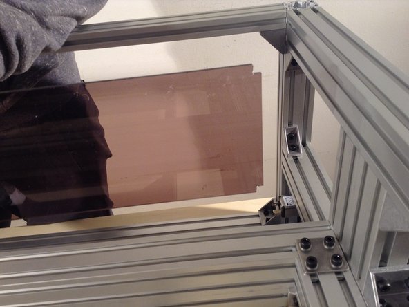
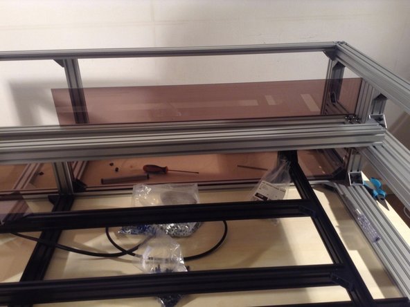
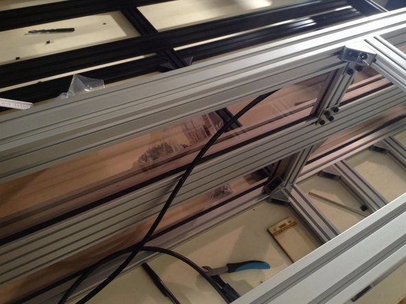
Cut rubber gasket to size for the long separator windows - 2 seams on top and bottom horizontals. See example of how the rubber gasket fits in the grooves of the aluminum extrusion.
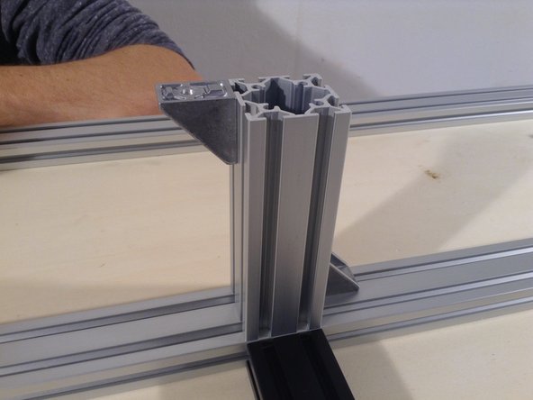
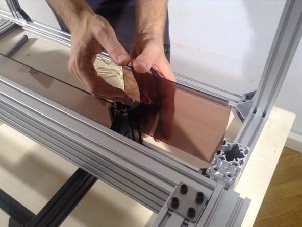
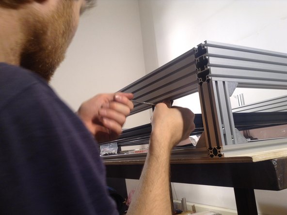
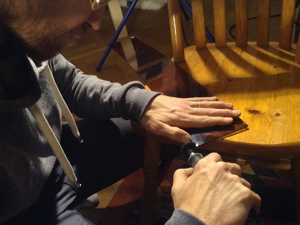
Insert rubber gasket in the bottom window edge. Poke in with the blunt end of a pen or some other object that helps the rubber to be pushed in the groove to create a tight seal.
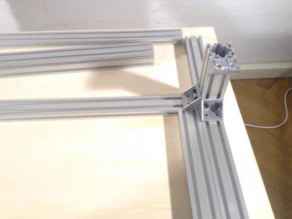
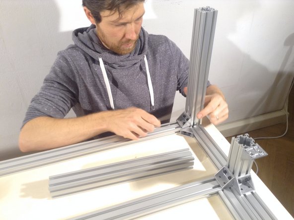
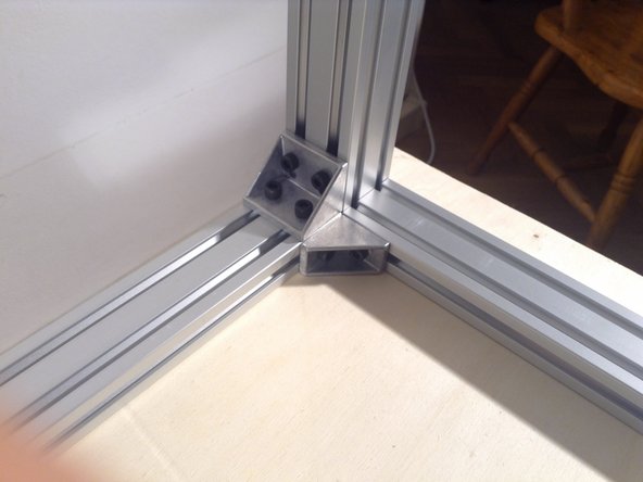
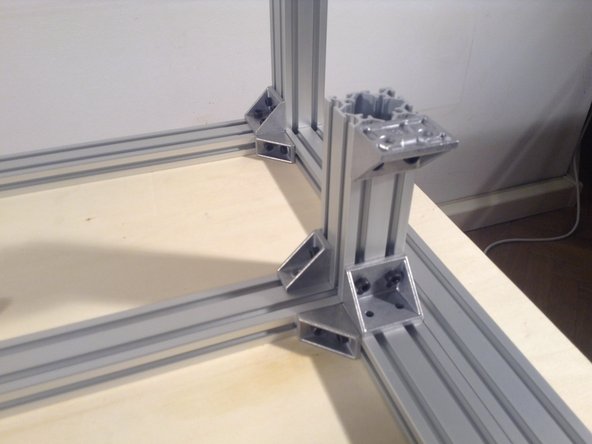
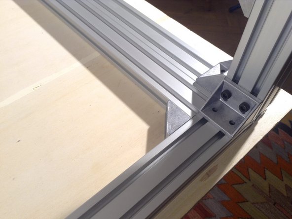
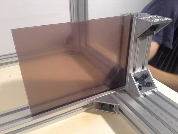
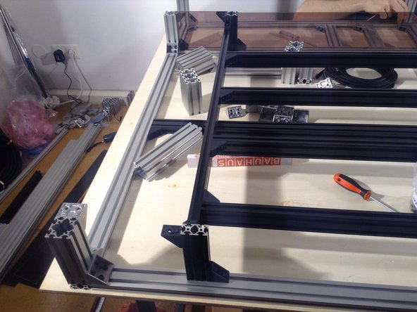
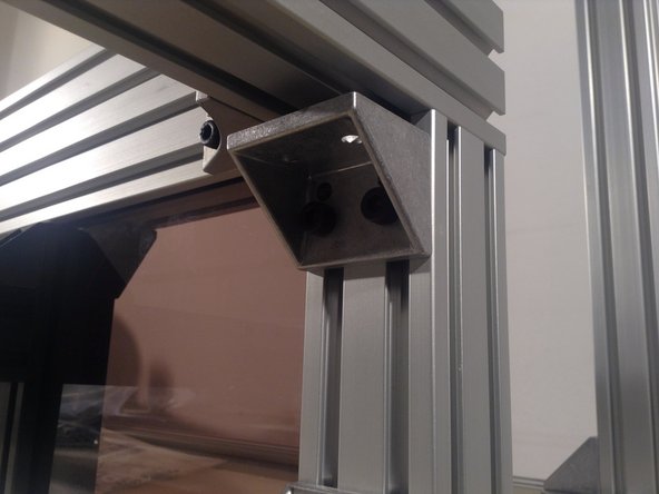
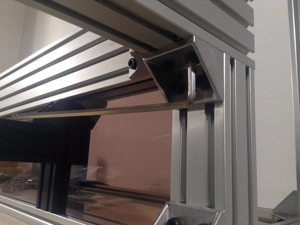
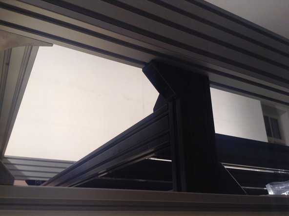
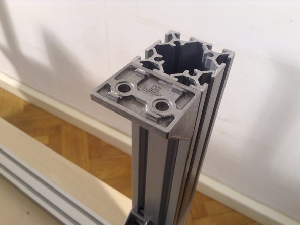
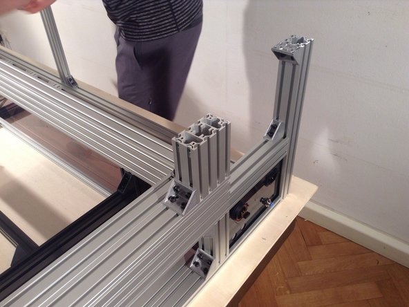
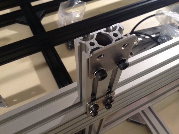
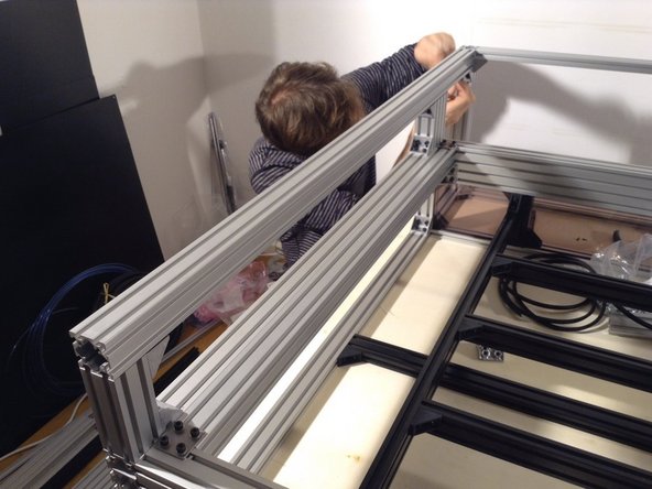
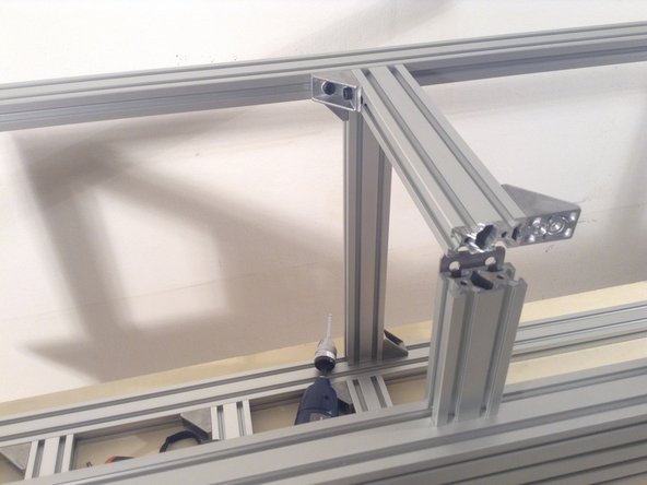
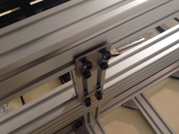
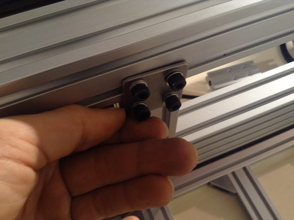
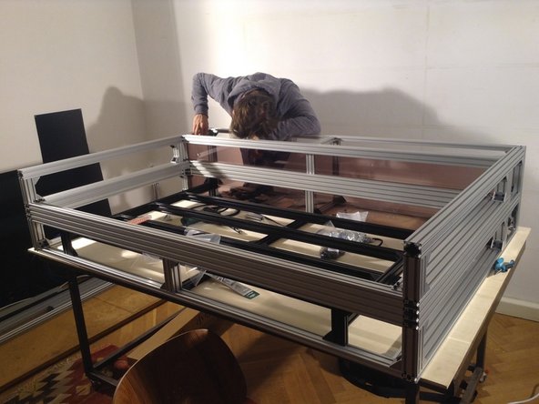
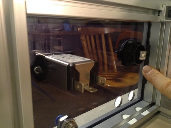
Use small bolts (8 mm long) and a washer for the flat double bracket. Before fixing this rear post in place, we need to install the back separator window.