Difficulty
Moderate
Steps
43
Time Required
05:00:00 - 06:00:00
- Backhoe Pivot for Stick and Boom 43 steps

In Progress
This guide is currently being written. Reload periodically to see the latest changes.

Private
This guide will not appear in search results and can only be viewed by team members!
Quiz
0
Introduction
OVERVIEW OF STEP PROCEDURE
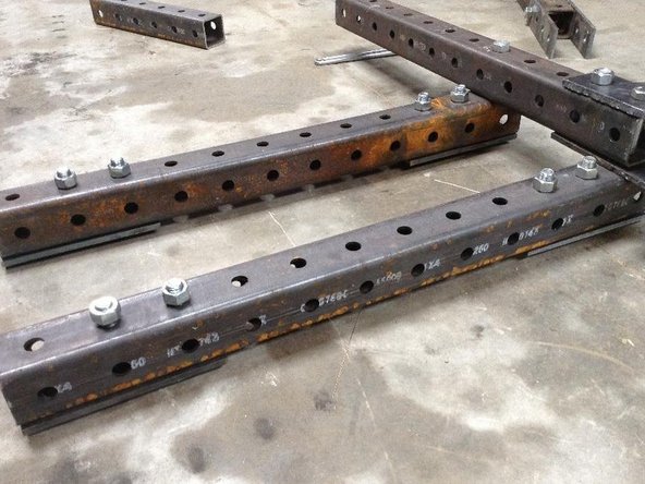
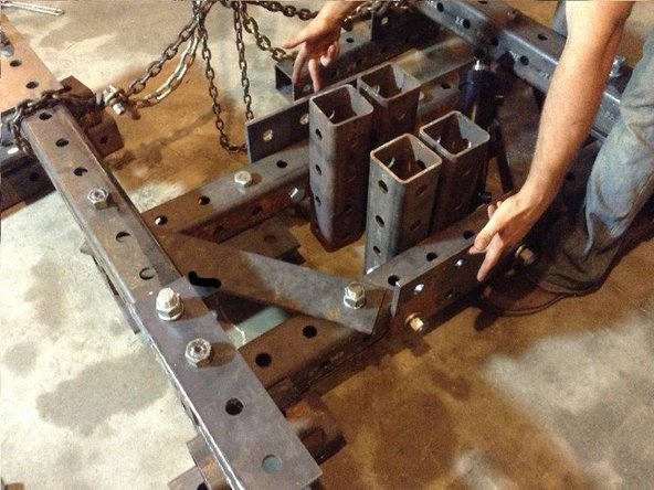
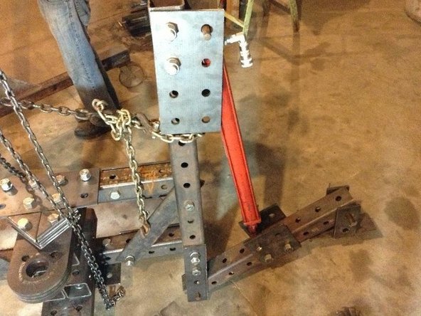
1 Take 4 12 hole tubes. 2 of these are the Leg Cylinder Tubes, and 2 are the quick attach plate tubes.
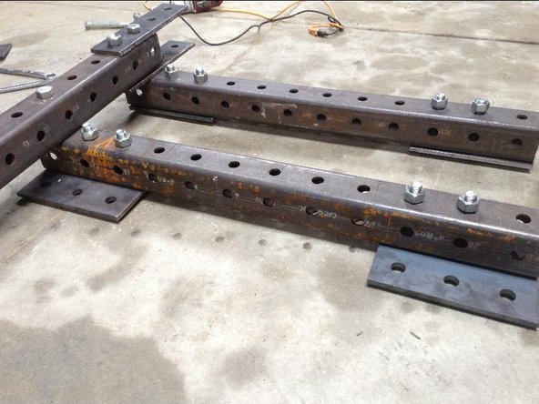
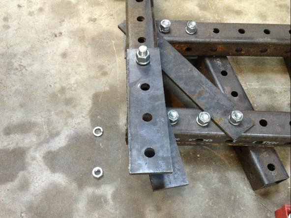
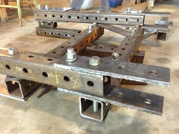
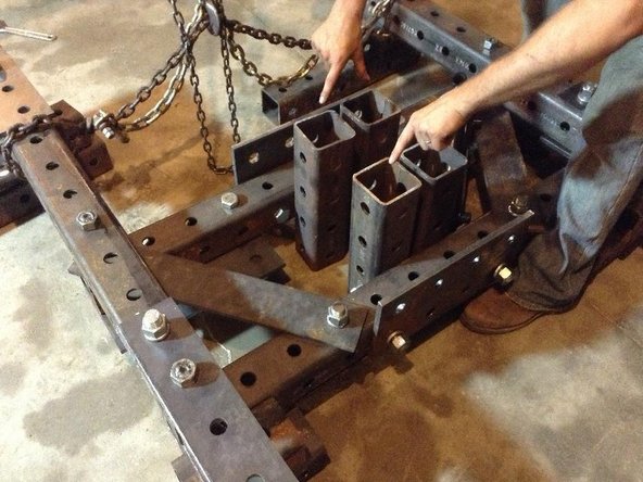
2 Mount the quick attach plate bottom 3 hole plates. Mount the quick attach plate top 2x3 hole plates. Use only the 2 of the 3 inner holes, as the third hole will be used to mount the leg cylinder tubes. Use 6 of 7" bolts, and use a 2" bolt for the Top Quick Attach Plate Tube. The 2 inch bolt is used to avoid conflict in mounting the angled support.
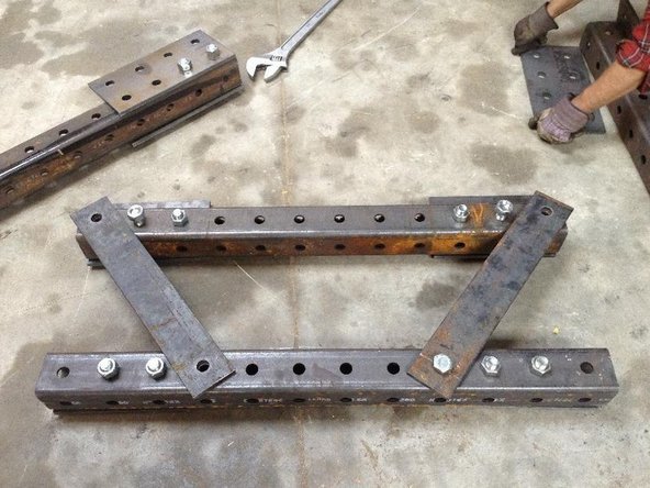
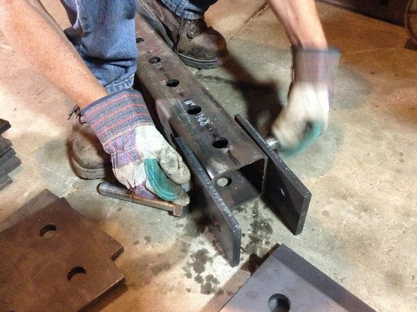
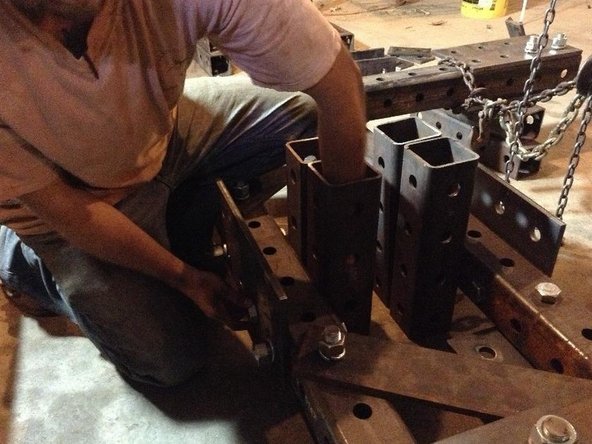
3 Cut the Angled support from a 24" piece of 1/2"x4" plate.
4 Install the Angled Support.
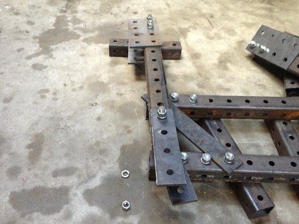
5 Install the Leg Cylinder Tubes.
Tools
Parts
-
-
Info on Step 1. Remember the journey of 1000 miles begins with a single step.
-
And we can...
-
add more lines...
-
Take 4 12 hole tubes. 2 of these are the Leg Cylinder Tubes, and 2 are the quick attach plate tubes.
-
-
-
Info about Step 2.
-
New line gives more details
-
Mount the quick attach plate bottom 3 hole plates. Mount the quick attach plate top 2x3 hole plates. Use only the 2 of the 3 inner holes, as the third hole will be used to mount the leg cylinder tubes. Use 8 of 7" bolts.
-
-
-
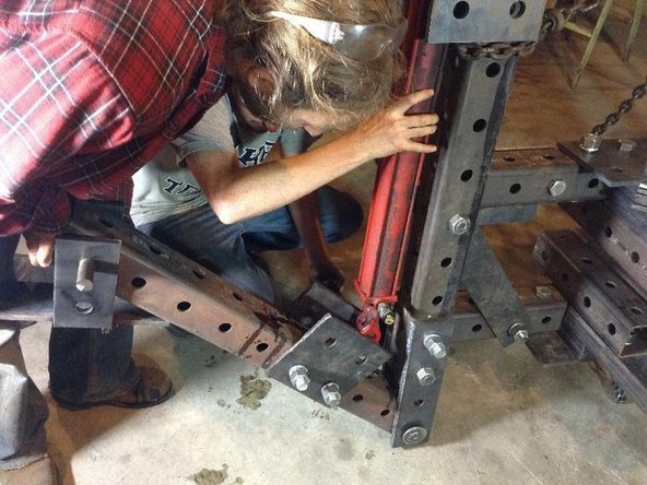
Build the Angled Support from a 24" piece of 1/2"x4" plate - then punch 2 holes at 20" spacing using a 1-1/16 bit in an open source Holepuncher Machine.
-
-
-
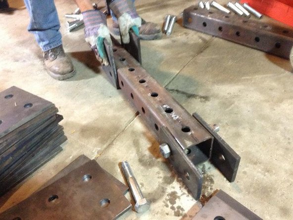
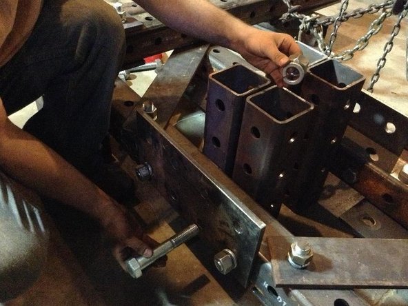
Install the 2 Angled Supports using 7 inch bolts, one on each side.
-
-
-
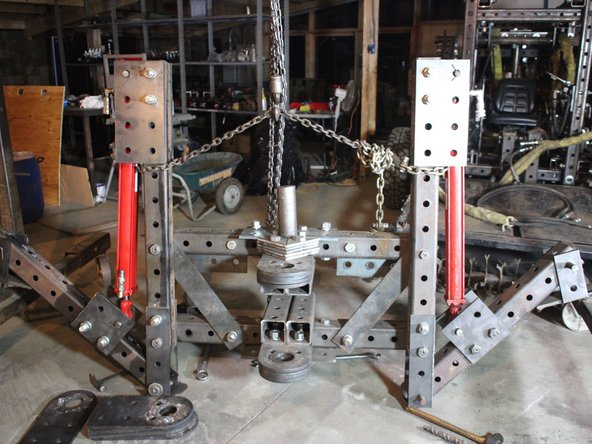
Install the 2 sets pf Upper Cylinder Mounts, on each side, with 7" bolts
-
-
-
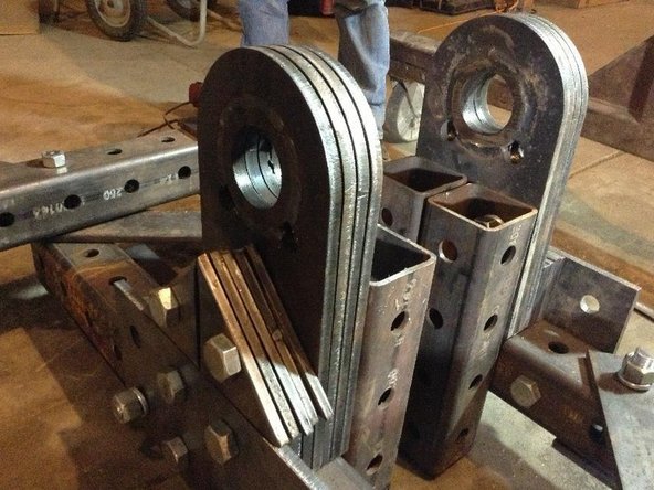
Install the Leg Pivot Plate, only on the upper hole with 7 inch bolt.
-
-
-
Use 4 11" bolts to mount the Leg Cylinder Tubes, where these tubes already have the Upper Cylinder Mounts and Leg pivot plates.
-
-
-
Attach feet holders to legs.
-
-
-
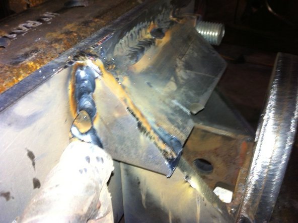
Weld feet and attach to legs
-
-
-
Attach bottom cylinder mounts to legs
-
-
-
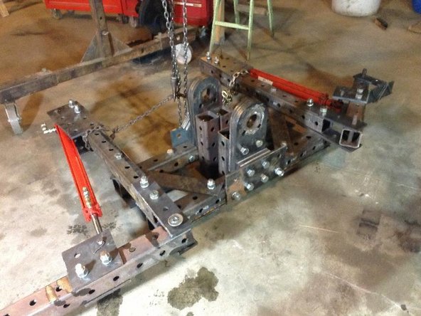
Attach Top Reinforcement Plate and Bottom Reinforcement Plate
-
-
-
Attach Main Pivot Tubes to Bottom Reinforcement Plate. Leave a space of 4" between them. Use 6" bolts to bond Reinforcement plates to the Main Pivot Tubes
-
-
-
Bolt in through the tube, bolt does not reach to the space between the Main Pivot Tubes.
-
-
-
add info for Step 14
-
-
-
Hold nut inside tube to do this.
-
-
-
Place Spacer Plates between the Bottom Reinforcement Plate and the Pivot Plates. Bolt these with 6" bolts
-
-
-
Bolt the Pivot Plates to the Main Pivot Tubes.
-
-
-
Step 18 wisdom
-
-
-
STep 19 ifo
-
-
-
Step 20
-
-
-
Step 21
-
-
-
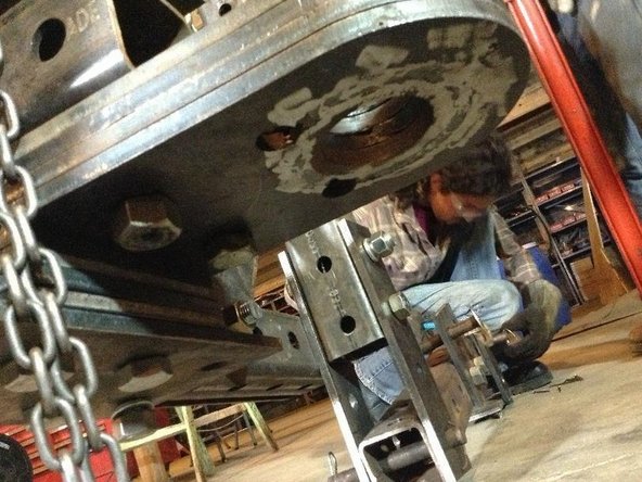
Zero - flip pivot upside down using a hoist
-
-
-
build cylinder bottom mount plates consisting of one by four whole plate pieces
-
-
-
cut bushings four-cylinder bottom mount and bolt cylinder mount one by fours to the pivot part one
-
-
-
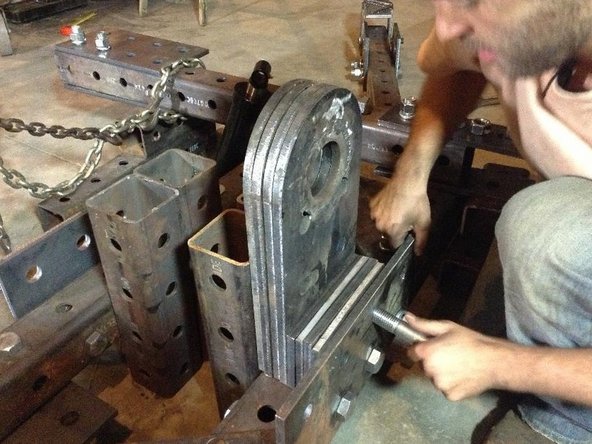
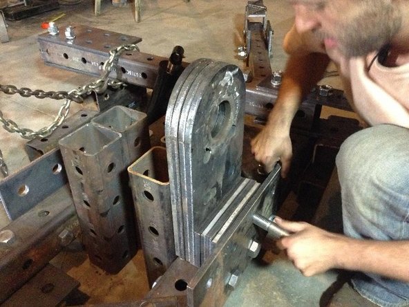
Cut 7.5 inch 1 inch shaft to size and weld a T handle on it consisting of a piece of 2" x 0.5" rebar
-
-
-
place cylinder in position and place shaft through Buesching and cylinder mount and through second Bushing
-
hold in place to where it will be welded put a small spacer underneath the rod and part of the cylinder to fit exactly within The 4 inch cavity of pivot part one.
-
The bushing location should be exactly 1.6 inches behind the & whole of the one by four hole plate, Or right behind the hole So that people can be put in the fourth hole of the one by four hole plate
-
-
-
Repeat for the second cylinder
-
-
-
Build cylinder rod and mount
-
-
-
take a 2 x 3 whole plate and notch out a space on the one and that is two and three-quarter inches from the edges and 2 inches deep.
-
-
-
Take a second plate which is an unfinished pivot plate and cut it down to 11 1/2 inches on the long side and cut off 1/2 inch from all sides to make it slightly smaller than the 3 x 2 whole plate
-
-
-
weld these two pieces together all around the edges for a solid fit.
-
-
-
Weld the 2 inch mounting bushings around the notch exactly 1.5 inches away from the edge of the 2 x 3 plate. Make sure that the spacing between them is exactly 2.25 inches or the width of the rod and cylinder tube. Weld with the shaft in place
-
-
-
weld the 2 x 3 gusset plate right in front of the cylinder mount bushings and weld solidly to the plate assembly. Do two of these per mounting plate.
-
-
-
repeat for the second cylinder
-
-
-
bolt the Rod and mount plate to pivot part two using short bolts. Do this only hand tight.
-
-
-
Put in the rod and mounting pin to make sure it fits
-
-
-
take off the Rob and mounting plate and put on two pivot plates. For mounting the boom
-
-
-
Bolt on the cylinder boom cylinder mounting assembly to the top of that part two
-
-
-
Mount the quick attach Finger assemblies on the tractor - at hole 10 on the front loader
-
-
-
Move tractor to the backhoe and put the upper quick attach finger weldment into place on both the right and left-hand sides Of the quick attach and tack into place
-
Add triangular support to side of finger for strength
-
-
-
Determine the location of the latch hole for the bottom quick attach part and torch it out
-
-
-
Put the bottom quick attach plate weldment into place on the backhoe and tack
-
-
-
Move tractor away and finish weld the quick attach plates on the Backhoe
-