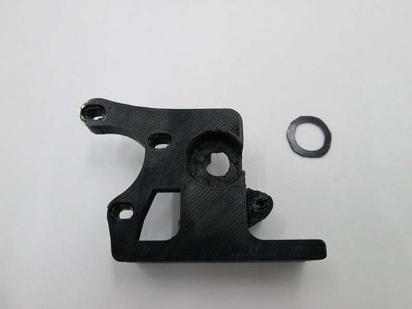
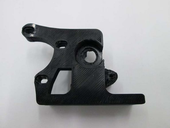
Parts
- Extruder Body
- Extruder Idler with 608 bearing installed
- Extruder Washer
- Large Herringbone Gear with Hobbed Bolt
- Small Herringbone Gear
- Extruder Latch
- Extruder Spring
- Motor - 2
- 608 Bearing
- M3 x 6mm Set Screw
- M3 x 12 SHCS
- M3 x 25 SHCS
- M3 Nut, Zinc
- M3 Washer
- M4 x 55 SHCS with Thumb Screw Knob
- M4 Nut, Zinc
- M4 Washer
- M8 Nylon Nut
- M8 Washer
- M8 Shim Washer 0.5
- M8 Shim Washer 1.0
-
-
Gather parts and tools for Extruder Assembly
-
Photo 1 - 1.5mm Allen Driver
-
Photo 2 - 2.5mm Allen Driver
-
Photo 3 - 13mm Wrench
-
-
-
INSTALL IDLER BOLT
-
Install M3 x 25 SHCS, M3 Washer and M3 Nut into the Idler assembly
-
Only put the screw in until the tip is flush with the nut
-
TIP: Set M3 Nut into the hexagon cutout and hold with your finer to install the bolt
-
-
-
INSTALL EXTRUDER WASHER INTO BODY
-
Place the printer extruder washer into the extruder body
-
-
-
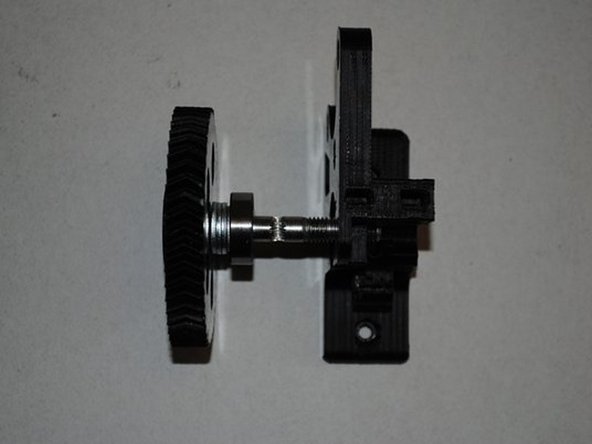
INSTALL GEAR, BOLT AND FIRST BEARING
-
Install 4 x M8 washers onto the hobbed bolt then a 608 bearing.
-
Once installed, does the hobbing on the bolt line up with the small hole going through the extruder body?
-
If you need to adjust it's location, you can add either a 0.50mm or 1.0mm shim washer to get the correct spacing.
-
Does the hobbing line up with the hole in the center?
-
-
-
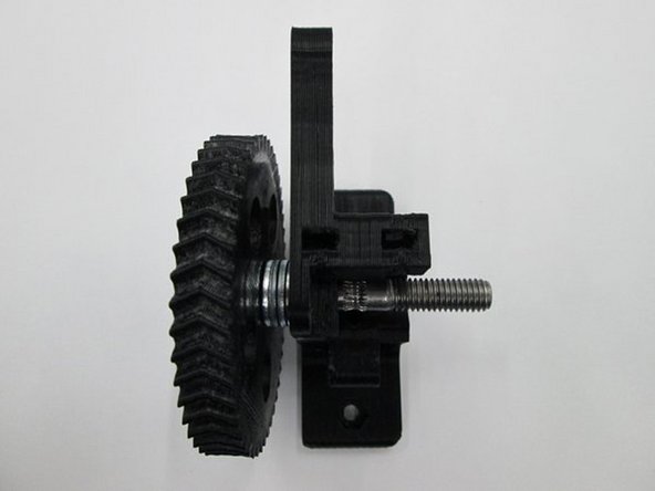
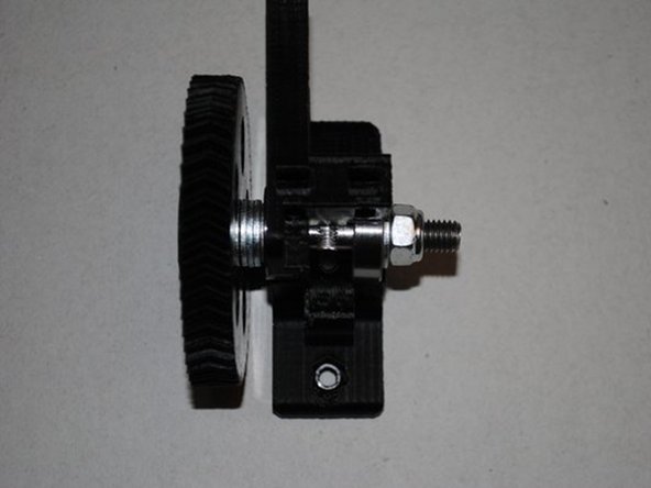
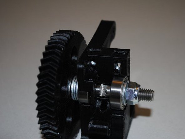
INSTALL SECOND BEARING
-
On the opposite side of the gear, add a 608 bearing, M8 Washer and a M8 locknut.
-
Tighten the Locknut down until the bearing is seated and there is no space between the Nut, Washer and Bearing.
-
The large gear shouldn't be able to rock back and fourth but should spin freely.
-
Does the gear turn freely?
-
Does the hobbing still line up with the hole in the body?
-
Record what type and how many washers were used.
-
-
-
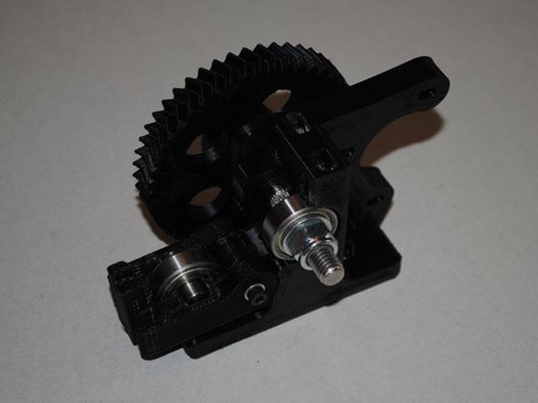
INSTALL IDLER ONTO BODY
-
Install extruder idler onto the body.
-
Tighten the M3 x 25, SHCS bolt down to secure the Idler
-
Tip: Place the leg with the nut on the body first and twist the Idler onto the body.
-
Does the Idler swing freely on the bolt?
-
-
-
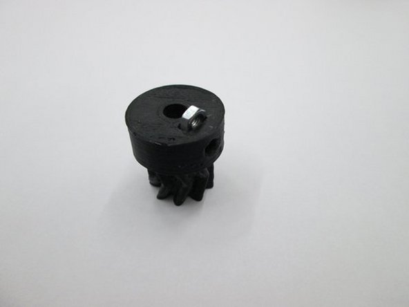
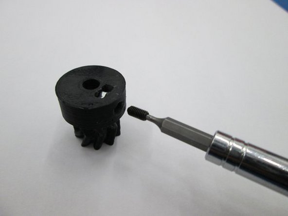
SMALL GEAR ASSEMBLY
-
Install the M3 nut into the bottom of the small herringbone gear.
-
Then install the M3 x 6mm set screw through the side of the small gear and into the nut.
-
Be sure the M3 x 6mm set screw does not protrude into the hole through the small gear.
-
-
-
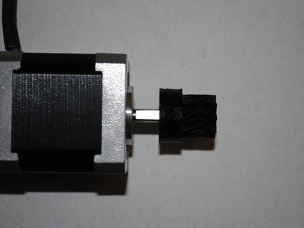
INSTALL GEAR ON MOTOR
-
Locate the flat side of the motor shaft.
-
With the set screw aligned with the flat, slide the small gear onto the motor shaft.
-
The location will be adjusted later so positioning isn't important at this point.
-
Do not tighten the set screw yet.
-
Is the set screw aligned with the flat?
-
-
-
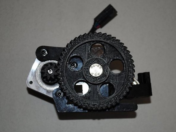
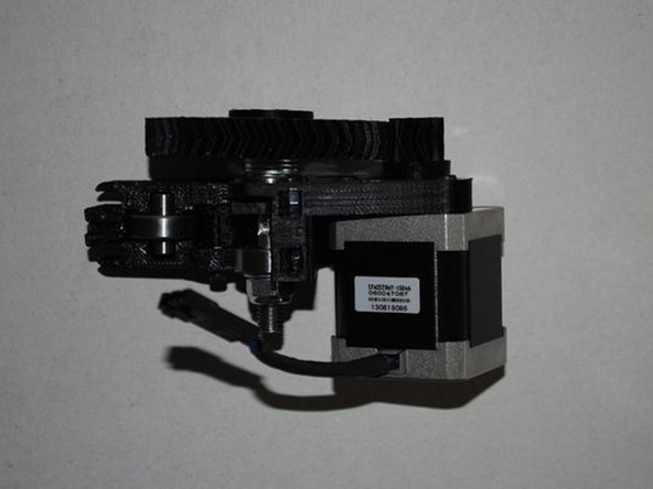
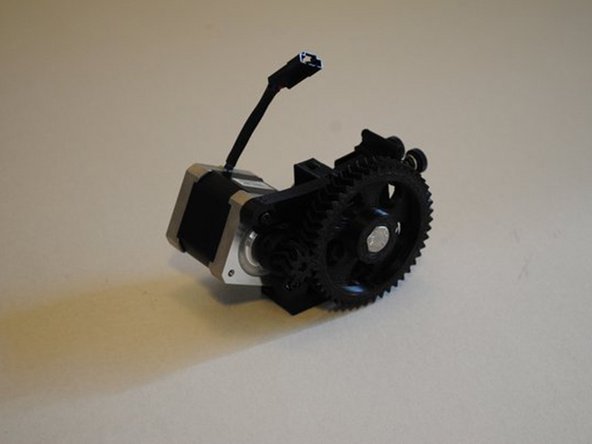
INSTALL MOTOR
-
Holding the motor in the location where it will be mounted, align the herringbone gears by sliding the small gear in or out on the motor shaft so the V-grooves are centered on each other.
-
Install motor using 3x M3 x 12mm SHCS and 3x M3 washers, taking note of the orientation of the motor wires.
-
Push the gears together while you tighten the bolts to make sure the contact is tight.
-
Tighten the set screw on the small herring bone gear.
-
Are the motor wires oriented correctly?
-
Are the V-grooves of the gears aligned?
-
Is there any back-lash in the gears? Can you spin the large gear for several rotations?
-
-
-
INSTALL M4 NUTS INTO TOP OF BODY
-
Install 2x M4 nuts into the top of the extruder body as shown.
-
Make sure you can see the nuts from the side so you can install bolts later.
-
Tip: Nuts only go in one way, the flats of the nut must be vertical.
-
Photo 1 - Nuts in body from top
-
Photo 2 - Nuts in body from side
-
-
-
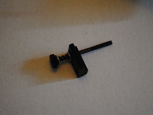
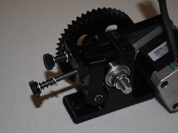
INSTALL IDLER TENSIONER
-
Install M4 x 55 with thumb knob, M4 washer, extruder spring, M4 washer and Extruder latch into M4 nut installed in body.
-
Then put another M4 x 55 with thumb knob, M4 washer, extruder spring, M4 washer through the Extruder latch and into the body.
-
Photo 1 - Prep parts for assemby
-
Photo 2 - Idler tensioner assembly
-
Can you adjust both bolts in and out by hand?
-
Can you swing the tensioner up and down?
-
-
-
REVIEW THE EXTRUDER ASSEMBLY
-